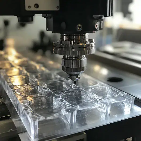
Gears transmit motion, torque, and power between rotating shafts in machines. In modern industry, many gears are produced through CNC machining manufacturing to ensure high precision and reliable performance.
In this guide, you will learn the most common types of gears, how they work, and where they are used in automotive, robotics, and industrial machinery.
What Is a Gear?
A gear is a mechanical component with evenly spaced teeth that rotates to transfer motion and power between shafts. When two gears mesh together, the teeth engage and allow one rotating gear to drive the other. This interaction makes it possible to control rotational speed, change torque levels, and redirect motion. Because of these capabilities, gears are widely used in gearboxes, engines, and various mechanical transmission systems.
Basic Parts of a Gear
A gear consists of several structural elements that ensure smooth power transmission. Key parts include the gear body, hub, bore, pitch circle, and gear teeth. These components work together to maintain proper alignment and load distribution during operation.
Gear Teeth and Tooth Elements
Gear teeth are the critical features that enable gears to transmit motion. Important tooth parameters include addendum, dedendum, pressure angle, and pitch line. These geometric features determine the strength, smoothness, and efficiency of gear engagement.
Functions of Gears in Mechanical Systems
The main function of gears is to transfer mechanical power between rotating shafts while controlling motion characteristics. Gears can increase or decrease speed, multiply torque, and change the direction of rotation. In some systems, gears can also convert rotational motion into linear motion.
How Gears Work?
Gears operate by interlocking teeth that transfer rotational motion between connected shafts. As one gear turns, its teeth engage with those of the mating gear, forcing the second gear to rotate as well. The relationship between their speeds and torque output is determined by the gear ratio, which depends on the number of teeth on each gear.
Power Transmission
Power transmission is the primary function of gears. By transferring rotational force from one shaft to another, gears enable machines to deliver mechanical energy efficiently across different components.
Speed and Torque Conversion
Gears control speed and torque through gear ratios.When a large gear turns a smaller gear, the smaller gear rotates faster but delivers less torque. In contrast, if a small gear drives a larger gear, the output rotates more slowly while producing greater torque.
Changing Direction of Motion
Gears can also change the direction of motion. Depending on their configuration, gears can reverse rotation direction or redirect power at different angles.
Gear Classification
Gears are mainly classified based on the orientation of the shafts they connect. The three main categories include gears for parallel shafts, intersecting shafts, and non-parallel non-intersecting shafts. Each classification determines how motion and power are transmitted between mechanical components.
Parallel Shaft Gears
Parallel shaft gears transmit motion and power between shafts that run parallel to each other. In this configuration, the gears mesh along the same plane, allowing efficient transfer of rotational motion with minimal energy loss. Because of their simple structure and stable performance, parallel shaft gears are widely used in many mechanical systems that require consistent speed and torque transmission.
Common examples of parallel shaft gears include spur gears and helical gears. Spur gears feature straight teeth aligned with the shaft axis, which makes them simple in design, highly efficient, and relatively easy to produce. In contrast, helical gears have teeth cut at an angle, allowing them to mesh more gradually. This design reduces vibration and noise while enabling the gear set to carry heavier loads, making parallel shaft gears widely used in industrial machinery and mechanical transmission systems.
Common characteristics of parallel shaft gears include:
• transmit motion between parallel rotating shafts
• provide high efficiency and stable power transmission
• common gear types include spur gears and helical gears
• suitable for high-speed and continuous operation
• widely used in gearboxes, industrial machines, conveyors, and automotive transmissions
Intersecting Shaft Gears
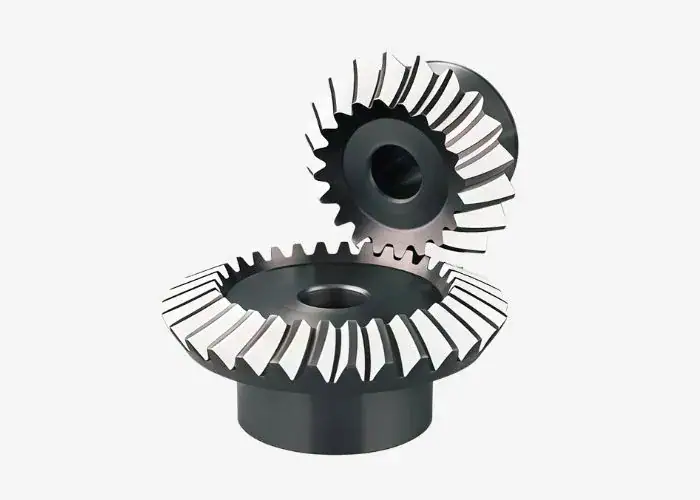
Intersecting shaft gears transmit motion and power between shafts whose axes intersect at a common point. This configuration is commonly used when rotational motion must be redirected at an angle, most often around 90 degrees. Because the shafts meet at a point, the gears are typically designed with a conical shape to maintain proper tooth engagement and smooth power transmission.
Bevel gears are the primary gear type used in intersecting shaft systems. They are commonly applied in mechanisms that require power to be transmitted between shafts that meet at an angle, such as automotive differentials, machine tools, and various industrial drive systems. Their conical geometry enables efficient motion transfer while redirecting the rotation to a different axis.
Common characteristics of intersecting shaft gears include:
• transmit motion between shafts that intersect at a point
• commonly operate at an angle, often around 90 degrees
• bevel gears are the most widely used type in this configuration
• suitable for changing the direction of power transmission
• commonly used in automotive differentials, machine tools, and industrial equipment
Non-Parallel and Non-Intersecting Shaft Gears
Gears for non-parallel and non-intersecting shafts are used when two shafts are positioned at different angles and do not meet at a common point. In such configurations, special gear designs are required to transfer motion and torque effectively between skewed shafts.
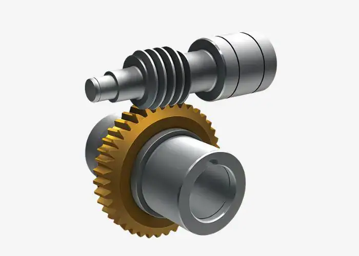
Typical examples include worm gears and hypoid gears. Worm gears use a screw-like worm that drives a worm wheel, allowing large speed reduction and smooth motion. Hypoid gears operate between offset shafts and are commonly used where compact layouts and efficient power transmission are required.
Common characteristics of non-parallel non-intersecting shaft gears include:
• transmit motion between shafts that are neither parallel nor intersecting
• suitable for transmitting power between skewed or offset shafts
• common types include worm gears and hypoid gears
• capable of achieving high reduction ratios and compact layouts
• widely used in automotive drive systems, gearboxes, and heavy machinery
Common Types of Gears
Several common gear types are used in mechanical systems, including spur gears, helical gears, bevel gears, worm gears, internal gears, rack and pinion systems, and planetary gears. Each type is designed to meet specific transmission requirements, such as adjusting rotational speed, transferring torque, or changing the direction of motion.
Spur Gears
Spur gears are among the most basic and widely used gear designs. They have straight teeth aligned parallel to the shaft, allowing them to mesh directly with another spur gear to transmit motion and power. Their straightforward structure makes them easy to manufacture and maintain, while also providing efficient power transmission in many mechanical applications.
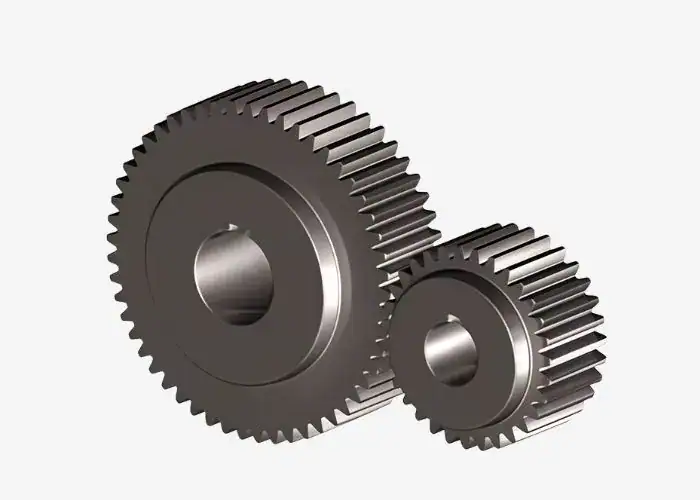
Spur gears operate with high efficiency because their teeth mesh fully across the gear width during rotation. However, the sudden tooth engagement can generate more noise and vibration at higher speeds compared with gear types such as helical gears. For this reason, spur gears are typically used in moderate-speed applications where efficiency and reliability are more important than quiet operation. For many gear manufacturers, spur gears remain a popular choice due to their simple design, ease of production, and consistent performance in a wide range of mechanical systems.
Common characteristics of spur gears include:
• straight teeth parallel to the shaft axis
• simple structure and easy manufacturing
• high transmission efficiency
• suitable for moderate speeds and loads
• widely used in gearboxes and industrial machinery
Spur Gear Overview
| Feature | Description |
| Tooth Shape | Straight teeth parallel to the shaft |
| Shaft Arrangement | Parallel shafts |
| Efficiency | Very high efficiency |
| Noise Level | Higher at high speeds |
| Typical Applications | Gearboxes, conveyors, machine tools |
Helical Gears
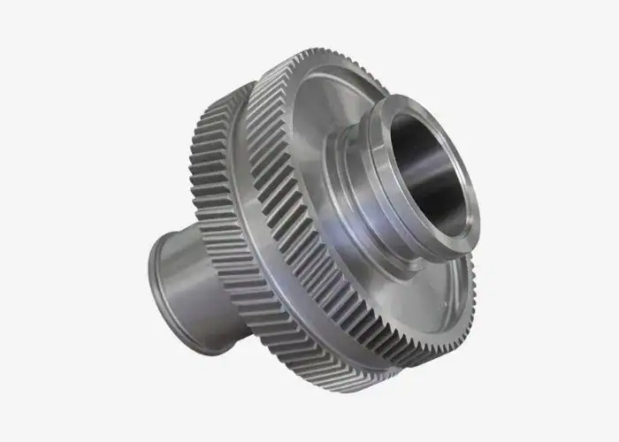
Helical gears have teeth that are cut at an angle to the shaft axis. This angled tooth profile allows the gears to mesh gradually during rotation, producing smoother power transmission and quieter operation compared with spur gears. The progressive contact between the teeth also enables helical gears to carry heavier loads and perform well in high-speed applications.
Because of these advantages, helical gears are commonly used in systems that require stable and continuous motion, such as automotive transmissions, industrial gearboxes, compressors, and heavy machinery. One characteristic of helical gears is that the angled teeth generate axial forces along the shaft, which typically require thrust bearings to support the load.
Common characteristics of helical gears include:
• angled teeth relative to the shaft axis
• smoother and quieter operation than spur gears
• higher load capacity due to gradual tooth engagement
• suitable for high-speed and heavy-duty applications
• widely used in gearboxes, automotive transmissions, and industrial equipment
Helical Gear Overview
| Feature | Description |
| Tooth Shape | Angled teeth relative to the shaft axis |
| Shaft Arrangement | Parallel shafts |
| Load Capacity | Higher than spur gears |
| Noise Level | Lower due to gradual engagement |
| Typical Applications | Automotive transmissions, industrial gearboxes, compressors |
Double Helical and Herringbone Gears
Double helical gears and herringbone gears are advanced variations of helical gears. They consist of two sets of helical teeth arranged in opposite directions on the same gear body. This mirrored tooth arrangement allows the axial forces generated by one helix to cancel those produced by the other, eliminating thrust loads on the shaft and improving overall stability.
Because of their balanced design, double helical and herringbone gears can transmit large amounts of power smoothly and efficiently. They are commonly used in heavy-duty machinery, marine propulsion systems, large gearboxes, and industrial power transmission equipment where high load capacity and smooth operation are critical. Herringbone gears are similar to double helical gears but feature a continuous V-shaped tooth pattern without a central gap.
Common characteristics of double helical and herringbone gears include:
• two helical tooth sets arranged in opposite directions
• axial thrust forces cancel each other
• high load capacity and stable power transmission
• smoother operation with reduced vibration
• commonly used in heavy-duty gear systems and large industrial machinery
Double Helical / Herringbone Gear Overview
| Feature | Description |
| Tooth Shape | V-shaped teeth formed by two opposite helices |
| Shaft Arrangement | Parallel shafts |
| Axial Force | Eliminated due to opposite helix directions |
| Load Capacity | Very high |
| Typical Applications | Marine drives, heavy machinery, industrial gearboxes |
Bevel Gears
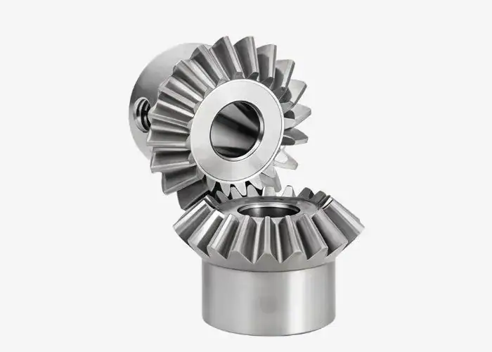
They are widely applied in mechanical systems that require a change in rotation direction, such as automotive differentials, machine tools, and industrial transmission equipment. Bevel gears are available in several forms, including straight bevel gears, spiral bevel gears, and miter gears, each designed for different performance requirements and operating conditions.
Common characteristics of bevel gears include:
• transmit motion between intersecting shafts
• usually operate at angles around 90 degrees
• conical gear shape for angular power transmission
• suitable for moderate to high load applications
• widely used in automotive differentials and industrial machinery
Bevel Gear Overview
| Feature | Description |
| Tooth Shape | Straight or curved teeth on a conical surface |
| Shaft Arrangement | Intersecting shafts |
| Direction Change | Commonly used to change motion direction |
| Load Capacity | Moderate to high depending on design |
| Typical Applications | Automotive differentials, machine tools, industrial drives |
Spiral Bevel Gears
Spiral bevel gears are a variation of bevel gears that feature curved teeth arranged in a spiral pattern along the conical gear surface. This design allows the teeth to mesh progressively during rotation, producing smoother motion and lower noise levels than straight bevel gears. The curved tooth profile also increases the area of contact between gears, which helps improve load capacity and enables stable operation at higher speeds.
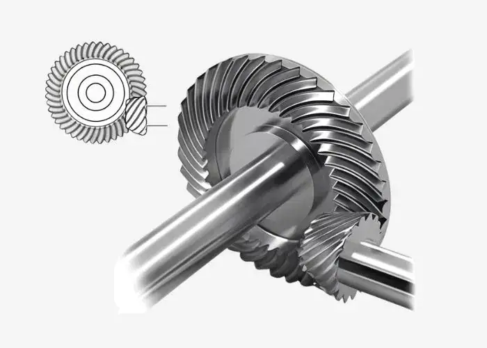
Because of their smooth operation and high load capacity, spiral bevel gears are widely used in demanding mechanical systems. They are commonly found in automotive differentials, heavy machinery, aerospace equipment, and industrial gear drives where quiet operation and reliable torque transmission are essential.
Common characteristics of spiral bevel gears include:
• curved teeth arranged along a spiral path
• smoother and quieter operation than straight bevel gears
• higher load capacity due to gradual tooth engagement
• suitable for high-speed power transmission
• widely used in automotive, aerospace, and industrial gear systems
Spiral Bevel Gear Overview
| Feature | Description |
| Tooth Shape | Curved spiral teeth on a conical surface |
| Shaft Arrangement | Intersecting shafts |
| Operation | Smooth and low-noise engagement |
| Load Capacity | Higher than straight bevel gears |
| Typical Applications | Automotive differentials, heavy machinery, aerospace systems |
Hypoid Gears
Hypoid gears resemble bevel gears but are designed for shafts that are offset rather than intersecting. In this arrangement, the pinion gear sits below or above the centerline of the driven gear, allowing the shafts to operate at different heights. This offset configuration enables smoother meshing, improved torque capacity, and quieter performance compared with standard bevel gears.
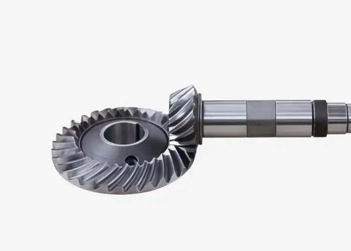
Hypoid gears are widely used in automotive drivetrains, particularly in rear axle differentials. Their design allows efficient power transfer while positioning the drive shaft lower in the vehicle, which can improve stability and space utilization. Because the gear teeth slide against each other during operation, proper lubrication is essential to minimize friction and wear.
Common characteristics of hypoid gears include:
• transmit motion between non-intersecting shafts
• pinion gear is offset from the center of the ring gear
• capable of handling high torque loads
• smoother and quieter operation than straight bevel gears
• widely used in automotive rear axle and differential systems
Hypoid Gear Overview
| Feature | Description |
| Tooth Shape | Spiral teeth on a hyperboloid surface |
| Shaft Arrangement | Non-intersecting, offset shafts |
| Load Capacity | High torque transmission capability |
| Operation | Smooth and quiet with sliding tooth contact |
| Typical Applications | Automotive rear axles, differential gear systems |
Miter Gears
Miter gears are a type of bevel gear used to transmit motion between intersecting shafts, usually at a 90-degree angle. Because both gears have the same number of teeth, they operate with a 1:1 gear ratio, allowing the direction of rotation to change without altering the speed.
Miter gears typically have straight or spiral teeth and are commonly used in mechanical systems that require simple right-angle power transmission. They are frequently found in machine tools, conveyor systems, printing equipment, and various industrial mechanisms where precise directional change is needed.
Common characteristics of miter gears include:
• bevel gears designed for a 1:1 gear ratio
• transmit motion between shafts at a 90-degree angle
• maintain the same rotational speed between gears
• simple and reliable right-angle power transmission
• commonly used in machine tools and industrial equipment
Miter Gear Overview
| Feature | Description |
| Tooth Shape | Straight or spiral bevel teeth |
| Shaft Arrangement | Intersecting shafts at 90° |
| Gear Ratio | 1:1 |
| Operation | Changes direction without changing speed |
| Typical Applications | Machine tools, conveyors, industrial equipment |
Worm Gears
Worm gears use a screw-shaped worm that meshes with a worm wheel to transmit motion between shafts that are neither parallel nor intersecting. This configuration allows large speed reduction ratios within a compact mechanism, making worm gears suitable for applications that require significant speed reduction and increased torque.
Another key feature of worm gears is their ability to provide self-locking in certain configurations. This means the worm wheel cannot easily drive the worm, preventing reverse motion in the system. Because of this property, worm gears are commonly used in lifting equipment, conveyor systems, elevators, and positioning mechanisms where controlled movement is important.
Common characteristics of worm gears include:
• consist of a screw-like worm and a worm wheel
• transmit motion between non-parallel, non-intersecting shafts
• capable of achieving high reduction ratios
• compact gear design suitable for limited space
• may provide self-locking capability in some applications
Worm Gear Overview
| Feature | Description |
| Tooth Shape | Screw-like worm engaging with a worm wheel |
| Shaft Arrangement | Non-parallel, non-intersecting shafts |
| Gear Ratio | Very high reduction ratios possible |
| Operation | Smooth and compact transmission |
| Typical Applications | Lifts, conveyors, elevators, industrial machinery |
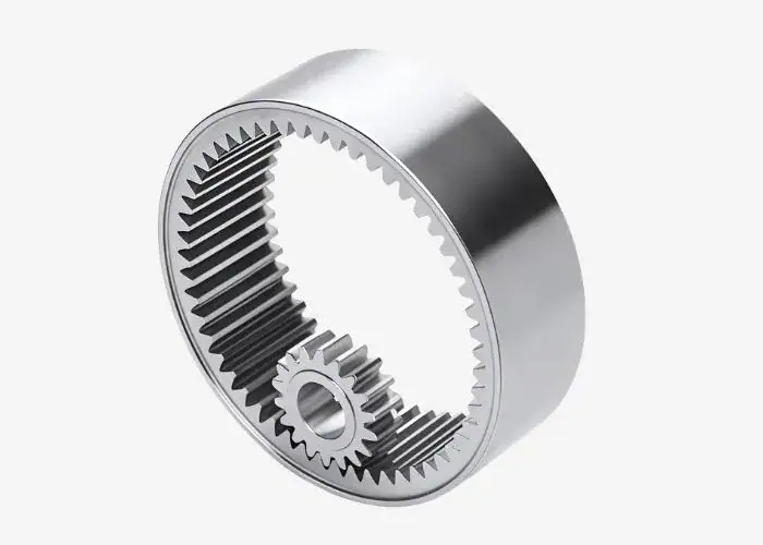
Internal Gears
Internal gears are gears with teeth cut on the inside surface of a cylindrical gear rather than on the outside. In this arrangement, the teeth mesh with a smaller external gear, allowing motion and power to be transmitted within a compact gear set. This design enables smooth power transfer while maintaining a compact mechanical layout.

Internal gears are most commonly used in planetary gear systems, where a central sun gear, multiple planet gears, and an internal ring gear work together to distribute load and transmit torque efficiently. Because of their compact structure and ability to handle high torque, internal gears are widely used in automotive transmissions, industrial gearboxes, and precision machinery.
Common characteristics of internal gears include:
• teeth cut on the inner surface of a cylindrical gear
• typically mesh with a smaller external gear
• commonly used in planetary gear systems
• compact design with efficient torque transmission
• widely used in gearboxes and automotive transmissions
Internal Gear Overview
| Feature | Description |
| Tooth Shape | Teeth located on the inner circumference |
| Shaft Arrangement | Usually part of planetary gear sets |
| Load Capacity | High torque capability |
| Operation | Compact and efficient transmission |
| Typical Applications | Planetary gear systems, automotive gearboxes, industrial machinery |
Rack and Pinion Gears
Rack and pinion gears convert rotational motion into linear motion. The system includes a circular pinion gear that meshes with a straight rack, and when the pinion rotates, it drives the rack to move in a straight line, enabling controlled and precise linear movement in mechanical systems.
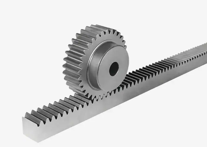
Rack and pinion systems are widely used in applications that require accurate linear motion. One of the most common examples is automotive steering systems, where the rotation of the steering wheel moves the rack left or right to control the wheels. They are also used in CNC machines, industrial automation equipment, elevators, and sliding mechanisms where controlled linear movement is needed.
Common characteristics of rack and pinion gears include:
• convert rotational motion into linear motion
• consist of a circular pinion gear and a straight rack
• provide precise and direct motion control
• suitable for positioning and steering mechanisms
• widely used in automotive steering, CNC machines, and automation equipment
Rack and Pinion Overview
| Feature | Description |
| Gear Type | Combination of pinion gear and straight rack |
| Motion Conversion | Rotational motion to linear motion |
| Operation | Direct and precise movement |
| Load Capacity | Moderate depending on design |
| Typical Applications | Automotive steering systems, CNC machines, automation equipment |
Planetary (Epicyclic) Gears
Planetary gears, also known as epicyclic gears, consist of a central sun gear, several planet gears mounted on a carrier, and an outer ring gear with internal teeth. The planet gears rotate around the sun gear while also revolving with the carrier, allowing multiple gears to share the transmitted load.
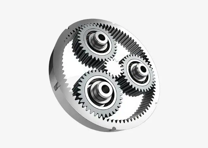
Because the load is distributed across several planet gears, planetary gear systems can transmit higher torque while maintaining a compact structure. This design provides smooth power distribution and high efficiency, which is why planetary gears are widely used in automatic transmissions, robotics, wind turbines, and industrial gearboxes.
Common characteristics of planetary gears include:
• consist of a sun gear, planet gears, and an internal ring gear
• multiple planet gears distribute the load evenly
• capable of transmitting high torque in compact spaces
• efficient and stable power transmission
• widely used in automotive transmissions, robotics, and industrial gear systems
Planetary Gear Overview
| Feature | Description |
| Gear Structure | Sun gear, planet gears, and internal ring gear |
| Load Distribution | Multiple planet gears share the load |
| Torque Capacity | Very high for compact size |
| Operation | Smooth and efficient transmission |
| Typical Applications | Automatic transmissions, robotics, wind turbines, industrial gearboxes |
Gear Materials and Design Considerations
Gear performance depends not only on the gear type but also on the materials used and the design parameters applied. Proper material selection improves strength, durability, and wear resistance, while good design ensures efficient and reliable power transmission. These factors are essential for maintaining stable gear operation in mechanical systems.
Common Materials Used in Gears
Gears are manufactured from different materials depending on load capacity, operating speed, and environmental conditions. The most commonly used materials include steel, cast iron, aluminum, and engineering plastics, each offering unique advantages in strength, durability, and weight.
Common gear materials include:
• steel – high strength and durability for heavy-duty applications
• cast iron – good wear resistance and vibration damping
• aluminum – lightweight material for moderate loads
• engineering plastics – low noise and corrosion resistance
Gear Tooth Design
Gear tooth design directly affects how smoothly gears transmit motion and torque. Factors such as tooth profile, pressure angle, and contact ratio influence efficiency, load distribution, and noise levels during operation.
Important gear tooth design factors include:
• tooth profile and geometry
• pressure angle and tooth spacing
• load distribution across the gear teeth
• smooth engagement between meshing gears
Lubrication and Precision Requirements
Proper lubrication and manufacturing precision are essential for maintaining gear performance and reducing wear. Lubrication minimizes friction and heat generation, while high precision ensures accurate gear meshing and stable motion transmission.
Key considerations include:
• selecting appropriate lubricants to reduce friction
• maintaining correct gear alignment
• ensuring high machining precision
• controlling surface finish and tolerance levels
Applications of Gears
Gears are widely used across many industries to transmit power, control motion, and adjust speed or torque in mechanical systems. Because of their efficiency and reliability, gears are essential components in everything from large industrial machinery to small consumer devices.
The following table highlights some of the most common industries where gears are applied and their typical functions:
| Industry | Typical Gear Applications |
| Automotive | Transmissions, differentials, steering systems |
| Industrial Machinery | Conveyors, turbines, manufacturing equipment |
| Robotics & Automation | Precision motion control systems |
| Aerospace | Aircraft engines, actuators, control systems |
| Consumer Products | Printers, home appliances, power tools |
Automotive Systems
Gears are essential components in automotive transmissions, differentials, and steering systems. They help control vehicle speed, distribute torque to the wheels, and convert rotational motion for steering mechanisms.
Industrial Machinery
Industrial machines use gears to transmit power and control motion in conveyors, turbines, gearboxes, and manufacturing equipment. They ensure reliable operation in heavy-duty mechanical systems.
Robotics and Automation
Robotic systems rely on gears to achieve precise motion control and accurate torque transmission. Gear mechanisms allow robotic arms and automated machines to move smoothly and perform complex positioning tasks.
Aerospace Equipment
Aircraft systems use gears in engines, actuators, and flight control mechanisms. These gears must operate with high precision and reliability under demanding conditions such as high speed and extreme loads.
Consumer Products
Many everyday products use gears to control motion and improve mechanical efficiency. Examples include printers, home appliances, power tools, and small electric devices where compact gear systems enable reliable performance.
How to Choose the Right Gear
Choosing the right gear requires evaluating several engineering factors, including torque, speed, efficiency, space constraints, and operating conditions. Selecting the appropriate gear type ensures reliable power transmission, longer service life, and optimal mechanical performance.
The table below summarizes key factors engineers typically consider when selecting gears:
| Selection Factor | Why It Matters |
| Load & Torque | Determines gear strength and durability |
| Speed | Affects gear efficiency and noise level |
| Space Constraints | Influences gear size and configuration |
| Cost | Impacts manufacturing and system budget |
| Maintenance | Determines lubrication and service needs |
Load and Torque Requirements
Engineers must calculate the expected load and torque to ensure the selected gear can handle operating forces without excessive wear or failure. Proper load analysis helps determine the appropriate gear size, material, and tooth design for safe and reliable performance.
Speed and Efficiency Considerations
Different gear types provide different levels of efficiency depending on operating speed and friction conditions. For example, spur gears are highly efficient at moderate speeds, while helical gears provide smoother operation at higher speeds with reduced noise.
Space Constraints
In compact mechanical systems, space limitations often influence gear selection. Planetary gears and worm gears are commonly used in space-constrained designs because they can provide high torque transmission within a relatively small footprint.
Cost and Maintenance Factors
Engineers must also consider manufacturing costs, lubrication requirements, and maintenance needs when selecting gears. Choosing a gear design that balances performance, cost, and long-term reliability is essential for efficient system operation.
FAQs
What Are The 5 Most Common Types Of Gears?
I usually identify five common gear types: spur gears, helical gears, bevel gears, worm gears, and planetary gears. Spur gears are simple and efficient, often reaching about 98% efficiency. Helical gears run more smoothly, bevel gears change motion direction, worm gears provide high reduction ratios, and planetary gears deliver high torque in compact systems.
What Are The Different Types Of Gears In Cars?
In cars, I commonly see helical gears, hypoid gears, bevel gears, spur gears, and planetary gears. Helical gears are used in transmissions for smooth operation. Hypoid gears handle high torque in rear differentials, while planetary gears enable multiple gear ratios in automatic transmissions.
What Are The 7 Types Of Gears In Physics?
In physics, I typically classify seven gear types: spur gears, helical gears, bevel gears, worm gears, rack and pinion gears, internal gears, and planetary gears. Each type helps transmit motion, change speed, or convert rotational movement into linear motion in mechanical systems.
Conclusion
Understanding the different types of gears helps engineers select the most suitable gear design for efficient power transmission, motion control, and long-term mechanical reliability. The right gear choice depends on factors such as load, speed, space constraints, and operating conditions.
At TiRapid, we support engineers with precision CNC machining for gears and complex mechanical components. Whether you need prototype gears or production parts, upload your design to receive a customized manufacturing solution.