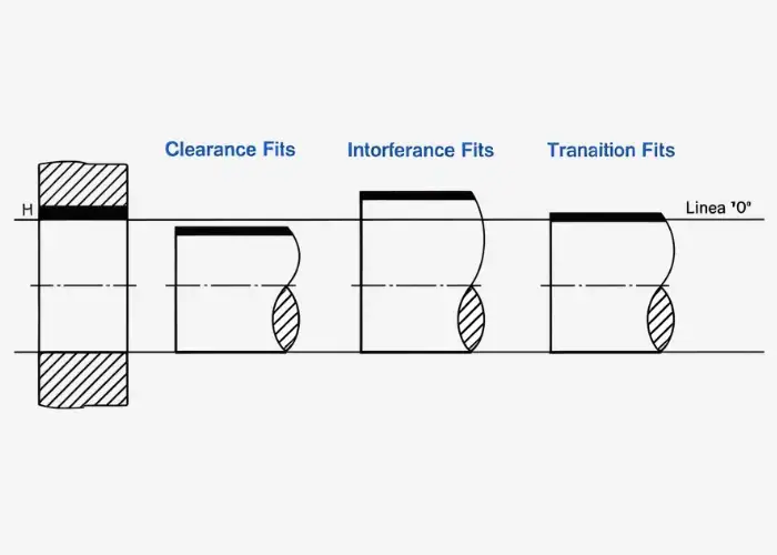
Types of fits describe how two mating parts fit together in an assembly. In engineering, the selected fit affects movement, alignment, assembly force, wear, and overall performance. The three main types of fits are clearance fit, transition fit, and interference fit.
In this guide, you’ll learn what types of fits are, how each fit works, when to use them, and how to choose the right fit for engineering applications.
What Is a Fit in Engineering?
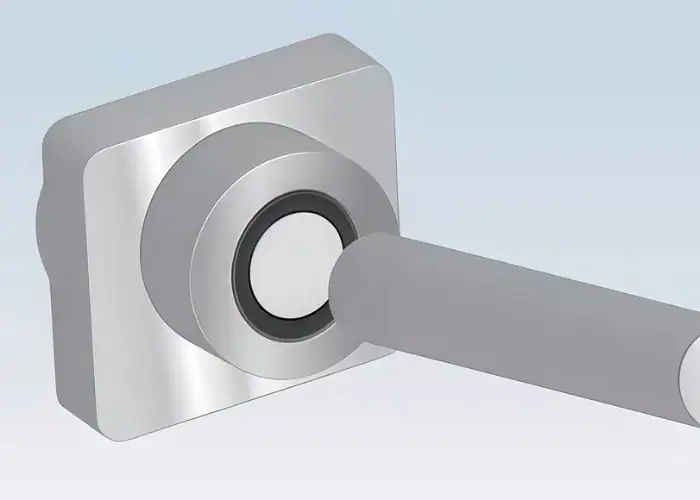
A fit in mechanical engineering is the dimensional relationship between two mating parts, usually a hole and a shaft. It determines whether the parts assemble with looseness, light resistance, or force, and defines the level of clearance or interference between them.
This relationship affects how parts behave in assembly and operation:
- Movement between parts
- Alignment and positioning accuracy
- Load transfer and contact conditions
- Assembly force requirements
That is why fit in mechanical engineering is closely linked to part function, assembly performance, and overall reliability.
Hole Basis and Shaft Basis Systems
The hole basis and shaft basis systems are the two standard ways to define engineering fits. In a hole basis system, the hole size stays constant and the shaft size changes. In a shaft basis system, the shaft stays constant and the hole size changes.
In practice:
- Hole basis system = More common
- Shaft basis system = Used when shaft size must stay fixed
The hole basis system is often preferred because standard hole-making tools are easier to keep consistent in production.
| System | What Stays Constant | What Changes | Typical Use |
| Hole Basis System | Hole size | Shaft size | Most common fit design method |
| Shaft Basis System | Shaft size | Hole size | Used when shaft size is fixed by design or process |
Relationship Between Fits and Tolerances
Fits and tolerances are related because fit is created by the tolerance limits of the mating parts. Tolerance defines the allowable size variation of each part, while fit defines the resulting clearance or interference after assembly.
A simple way to understand it is:
- Tolerance controls size variation
- Fit controls assembly behavior
- Both must work together
This is why types of fits and tolerances are usually specified together in engineering drawings and standards. ISO 286 and ANSI fit systems are commonly used to communicate those relationships.
What Are the Three Main Types of Fits?
The main types of fits are clearance fit, interference fit, and transition fit. These three types describe whether the shaft is always smaller than the hole, always larger than the hole, or may be slightly smaller or larger depending on the tolerance zone.
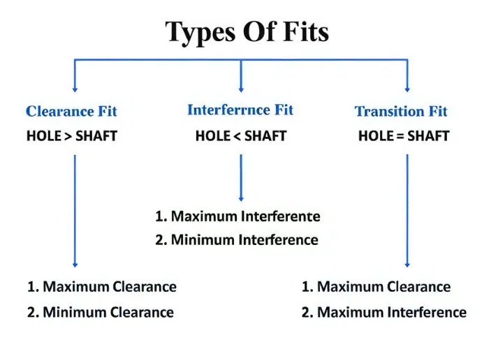
Clearance Fit
A clearance fit is a fit in which the shaft is always smaller than the hole, so there is always space between the parts after assembly. This makes movement or easy assembly possible.
Clearance fit is commonly used for:
- Rotating shafts
- Sliding components
- Removable assemblies
- Guide mechanisms
A sliding fit is a common example of clearance fit because it allows controlled movement without excessive looseness.
Interference Fit
An interference fit is a fit in which the shaft is always larger than the hole, so the parts must be pressed, heated, or cooled for assembly. This creates a firm connection that resists relative movement.
Interference fit is often used for:
- Gears on shafts
- Hubs
- Bushings
- Bearing seats
- Permanent or semi-permanent joints
Depending on the amount of overlap, it may also be called a press fit, force fit, or shrink fit.
Transition Fit
A transition fit is a fit that may result in either a small clearance or a small interference, depending on the actual part sizes within their tolerance limits. It sits between clearance fit and interference fit.
Transition fit is useful for:
- Accurate positioning
- Light press assembly
- Precision locating parts
- Assemblies needing limited play
It is typically chosen when better alignment is needed, but a strong press fit is unnecessary.
| Fit Type | Basic Condition | Assembly Behavior | Typical Use |
| Clearance Fit | Shaft smaller than hole | Free or controlled movement | Shafts, guides, sliding parts |
| Transition Fit | Small clearance or small interference | Accurate location with limited play | Dowel pins, precision assemblies |
| Interference Fit | Shaft larger than hole | Tight, force-based assembly | Gears, hubs, bearing seats |
When Should You Use Each Type of Fit?
Each type of fit should be selected according to the functional requirements of the assembly and the intended relationship between the mating parts after assembly. In general, a clearance fit is used when relative motion is required, an interference fit is used when secure retention is required, and a transition fit is used when accurate positioning is needed with minimal clearance or interference.
Applications of Clearance Fit
Clearance fit should be used when parts need free or controlled movement after assembly. Because the shaft is always smaller than the hole, there is always some space between the mating parts, which allows motion and makes assembly easier. This type of fit is commonly used in bearings, rotating shafts, sleeves, guide parts, and other components that need to move smoothly without excessive friction.
Best suited for:
- Rotation
- Sliding
- Frequent assembly and disassembly
- Lower assembly force
Clearance fit is often chosen when ease of movement matters more than holding force. Depending on the amount of clearance, it can support either freer motion or more controlled movement, such as in a sliding fit.
Applications of Interference Fit
Interference fit should be used when parts must remain firmly joined and resist movement under load. In this type of fit, the shaft is larger than the hole, so the parts must be pressed, heated, or cooled during assembly. This creates a tight connection that can transmit force and prevent slipping during operation. It is commonly used in gears, pulleys, hubs, bushings, and mounted bearings.
Best suited for:
- Torque transmission
- Strong retention
- Vibration resistance
- Permanent or semi-permanent joints
Interference fit is usually selected when holding strength and stability are more important than easy disassembly. The required level of interference depends on the material, part size, and service load.
Applications of Transition Fit
Transition fit should be used when accurate positioning is important and only a small amount of clearance or interference is acceptable. This fit falls between clearance fit and interference fit, so the assembly may feel slightly loose or slightly tight depending on the actual dimensions of the parts. It is commonly used in dowel pins, locating components, precision bearing fits, and other assemblies that require reliable alignment.
Best suited for:
- Accurate alignment
- Moderate assembly force
- Precision positioning
- Limited movement
Transition fit is often chosen when engineers need better positional control than a clearance fit can provide, but do not want the stronger holding force of an interference fit. It offers a practical balance between assembly convenience and alignment accuracy.
How Do You Choose the Right Fit in Engineering?
Selecting the right fit in engineering requires balancing assembly function, load, material behavior, tolerance capability, manufacturing limits, and cost. The most appropriate fit depends on the specific application rather than a single general rule.
Function of the Assembly
The function of the assembly determines whether the parts need motion, alignment, or locking. If the part must move, use clearance fit. If it must stay fixed, use interference fit. If it must locate accurately, use transition fit.
Load and Stress Conditions
Load and stress conditions affect fit choice because high torque, vibration, impact, or repeated loading can cause slipping or wear if the fit is too loose. Tighter fits are generally used when service loads are higher.
Material Properties
Material properties matter because soft materials can deform, brittle materials can crack, and different materials expand differently with temperature. The same nominal fit may behave differently in steel, aluminum, or plastic.
Manufacturing Tolerances and Capabilities
Manufacturing tolerances and capabilities matter because the intended fit can only be achieved if the process can produce the required dimensions consistently. Tight fits usually require tighter machining control and more inspection.
Assembly, Maintenance, Cost, and Standards
Assembly, maintenance, cost, and standards matter because some fits are easy to assemble and service, while others require pressing, heating, or special tooling. Tighter tolerances also increase machining cost and lead time, so the best fit is usually the one that meets function without unnecessary manufacturing difficulty.
| Selection Factor | Why It Matters |
| Function | Determines whether motion, location, or locking is needed |
| Load and Stress | Affects slipping risk, wear, and required holding force |
| Material | Changes deformation, expansion, and assembly behavior |
| Manufacturing Capability | Limits how tightly dimensions can be controlled |
| Assembly and Maintenance | Affects ease of installation and serviceability |
| Cost and Standards | Influences practicality, communication, and production efficiency |
What Are Some Real-World Examples of Fit Selection?
Real-world examples of fit selection show that different assemblies require different fit strategies. Bearings, gears, shafts, dowel pins, and guides all use different fits based on function and load.
Typical examples include:
- Bearing on a shaft: often selected for balance between running performance and secure mounting
- Gear on a shaft: often uses interference fit to prevent slip under torque
- Dowel pin: often uses transition or light interference fit for positioning
- Guide component: often uses sliding fit for controlled motion
These examples show that fit selection is always application-driven rather than size-driven alone.
What Questions Do Engineers Commonly Ask About Fits?
Engineers commonly ask about fits when they need to understand fit categories and tolerance codes. Common questions often involve sliding fit, H7, H7/g6, and F7 tolerance designations.
Quick answers:
- Sliding fit = a controlled clearance fit
- H7 = a commonly used hole tolerance zone
- H7/g6 = a standard hole-and-shaft fit designation
- F7 = a tolerance designation used in fit systems
These questions are common because engineers need both the fit type and the coded tolerance system to make the right design choice.
How Can You Choose the Right Fit More Confidently?
Choose the right fit more confidently by starting with function, then checking material behavior, tolerance capability, assembly method, and service conditions before finalizing the fit callout. In engineering practice, fit selection is not a single-step decision but a structured process that connects design intent with manufacturing reality.
A practical fit-selection checklist is:
- Use clearance fit for motion
- Use interference fit for secure retention
- Use transition fit for accurate positioning
- Confirm material compatibility
- Confirm process capability
- Confirm assembly and maintenance needs
- Avoid tighter tolerances than the design actually requires
In addition to these basic rules, engineers should also consider how the fit behaves under real operating conditions. Factors such as temperature variation, lubrication, wear over time, and vibration can change how a fit performs after assembly. A fit that works well in theory may behave differently in long-term service if these factors are not considered.
It is also important to think about production consistency. Even if a fit works in a prototype, it must be repeatable across batches. This means selecting tolerance ranges that can be maintained reliably by the chosen manufacturing process, rather than relying on overly tight or unrealistic specifications.
Another key point is design efficiency. Over-specifying a fit often increases machining time, inspection effort, and cost without improving performance. A well-chosen fit meets functional requirements while keeping manufacturing practical and economical.
When these factors are considered together, the selected fit is far more likely to perform reliably in both production and real-world service conditions.
FAQs
What Is A Sliding Fit?
A sliding fit is a type of clearance fit that allows two mating parts to move with controlled looseness. It is commonly used in shafts, sleeves, guides, and other assemblies that require smooth motion and reasonable positional accuracy.
What Type Of Fit Is H7?
H7 is not a complete fit by itself. It is a hole tolerance designation in the ISO system and is usually combined with a shaft tolerance to form a clearance fit, transition fit, or interference fit.
What Is H7 And G6?
H7 and g6 are standard hole and shaft tolerance designations. When used together as H7/g6, they typically form a clearance fit suitable for assemblies that require controlled movement and reliable alignment.
What Is F7 Tolerance?
F7 is a hole tolerance designation in a standard fit system. The letter shows the tolerance position, and the number shows the tolerance grade. Its final fit depends on the shaft tolerance paired with it.
What Are The Common Standards For Fits And Tolerances, And How Do They Differ?
The most common standards are ISO and ANSI. ISO systems use designations such as H7 and g6, while ANSI systems use different fit classes and are more common in inch-based applications.
How Do I Calculate The Required Tolerance For A Specific Fit?
The required tolerance is determined by the fit type, nominal size, and allowed clearance or interference range. In practice, engineers usually use standard fit tables to select suitable hole and shaft tolerances. For example, if a design uses an H7/g6 combination for a 20 mm shaft and hole, it is typically intended to produce a clearance fit for controlled movement and reliable alignment.
Conclusion
Types of fits help engineers control how mating parts assemble, move, and perform in real applications. The right fit selection depends on factors such as assembly function, material properties, tolerance requirements, manufacturing capability, and service conditions.
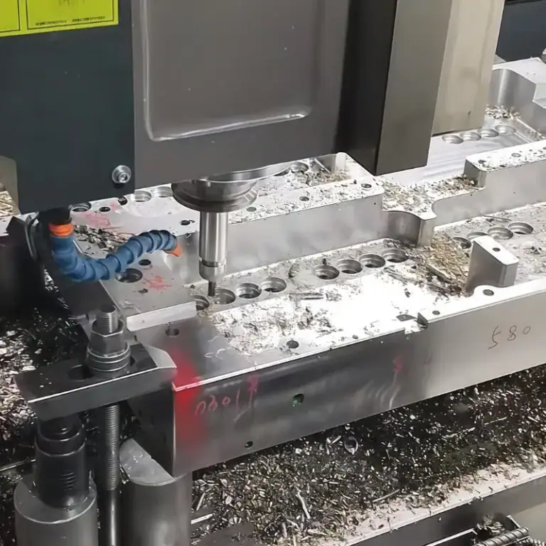
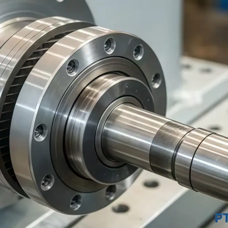
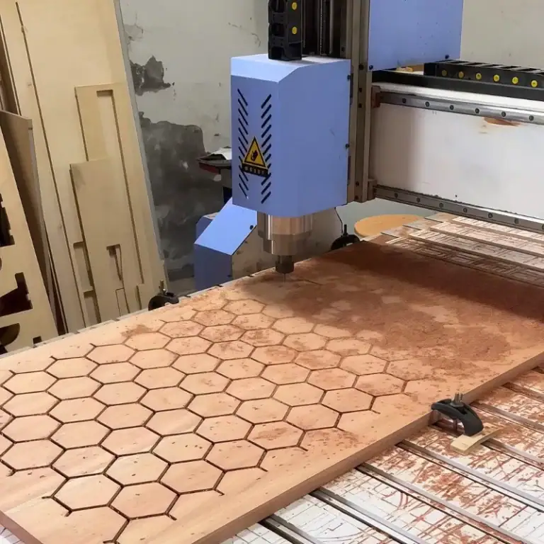
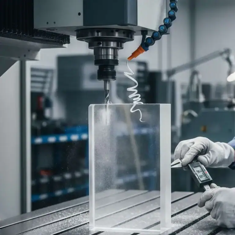
At TiRapid, we provide precision CNC machining for custom parts with fit-critical features across multiple industries. Upload your design to get a tailored solution for your engineering project.