In CNC machining, turning operations is the most basic but most critical part. From standard external turning to complex threading, grooving and tapping, each operation has its own unique process logic and application scenarios. I will take you to systematically understand 20 common turning types, from principles to parameter settings, to help engineers accurately select and process efficiently.
What Is Turning
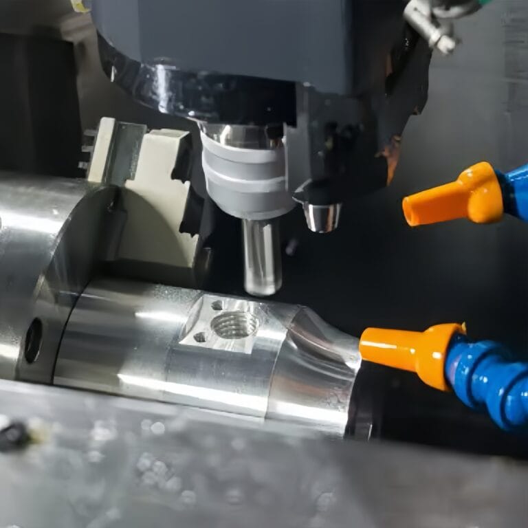
Turning is the process of cutting by rotating the workpiece and feeding the tool relative to it. It is suitable for all symmetrical rotating parts. From medical microneedles with a diameter of 0.5 mm to industrial sleeves with a diameter of 500 mm, I have achieved the whole process from rough machining to fine machining through turning.
According to statistics, more than 65% of the metal parts in our workshop undergo at least one turning process.
Why is it so common? Because turning is not only efficient, but also can stably achieve a dimensional tolerance of ±0.01mm or even ±0.005mm. With the right tools and programming strategies, it can also control the surface roughness Ra<0.8μm, meeting the needs of high-standard industries such as aviation, medical, and optics. To truly master turning, you must start with four core links: workpiece clamping, tool installation, cutting control, and quality inspection. Let me talk about them one by one.
Workpiece Clamping
The first step of turning is to firmly fix the raw material on the machine tool. The clamping methods we commonly use are three-jaw chuck, four-jaw chuck, hydraulic clamp or spring collet. The specific choice depends on the material size, shape and processing accuracy requirements. For example, when processing stainless steel thin-walled sleeves, I prefer to use a customized soft-jaw chuck with a tailstock support to prevent clamping deformation. If the clamping eccentricity exceeds 0.01mm, it will directly affect the final processing accuracy.
Tool Installation
Turning tools are roughly divided into external turning tools, internal turning tools, grooving tools and threading tools. I usually combine them according to the characteristics of the parts and the wear resistance of the tools. The tool tip height must be strictly aligned with the center of the workpiece during installation, otherwise there will be taper errors or tool edge breakage. We use the tool setting instrument to accurately set the tool coordinate system, and use the calibration rod to verify repeatedly to ensure that each tool can accurately cut into the processing path.
Cutting Process
In the actual cutting process, spindle speed, feed rate and cutting depth are the three core parameters. For example, when turning aluminum alloy parts, I will use a high-speed spindle of more than 3000 rpm to improve the surface quality; while machining titanium alloys requires reducing the speed and controlling the feed rate between 0.05–0.1mm/rev to prevent heat accumulation from burning the tool. To avoid vibration, I often use negative rake angle tools in the roughing stage to improve rigidity, and choose positive rake angle tools in the finishing stage to improve the finish.
Quality Inspection And Post-Processing
After turning, each part will enter the quality inspection stage. We mainly use vernier calipers, micrometers, CMM coordinate measuring machines and roughness meters for size and surface inspection. For parts with key dimensional tolerances less than ±0.01mm, I will conduct 100% inspection and keep records. Some high-demand workpieces also require subsequent polishing, deburring or heat treatment to achieve the final functional and appearance standards.
This is my basic understanding of turning technology. Each seemingly simple cut actually contains a high degree of control over clamping, tools, parameters and testing. If you want to achieve the ultimate in turning, it is not enough to just understand the principles, but you must also continuously optimize every detail in practice.
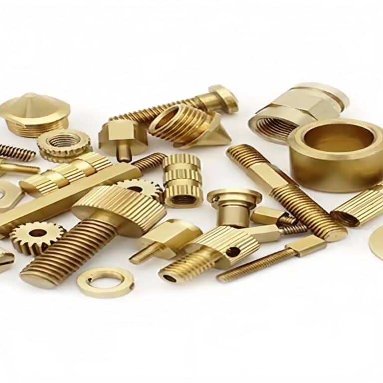
20 Common Types Of Turning Operations
In the CNC machining projects I have participated in, more than 70% of the rotating parts require a combination of multiple turning operations to achieve the target shape and function. You may think that “turning” is just cutting an outer circle or drilling a hole, but in fact, the operations in this field are far more than that. According to our machining data statistics over the past three years, on average, each precision shaft part involves at least 6 different turning operations . Each operation – whether it is rough turning, chamfering, taper turning, or threading, knurling, grooving – carries specific machining purposes and technical requirements.
For example, step turning can quickly create structural steps; taper turning is suitable for tapered fit; and thread turning needs to match standard tooth profiles and tolerance grades. I once encountered a complex medical device part that used 10 turning sub-operations in just one program , involving tolerance control, surface finish and strength matching, and every step could not go wrong. In order to efficiently respond to these diverse needs, we will accurately call the corresponding tool path and strategy during CAM programming based on the functional structure of the part .
The following is a classification of the 20 types of turning operations that I use most frequently in daily processing. You can understand it as the “core grammar library” of CNC turning operations – master them, and you will master the language of turning :
General Turning
In daily processing, ordinary turning is almost one of the most common basic operations I use. Whether it is machining shafts, sleeves or flanges, it is the starting point. The essence of turning is to achieve the size processing of the outer circle or inner hole by rotating the workpiece and feeding the single-edge tool along a straight line. The 3-axis and 5-axis CNC lathes commonly used in our workshop can control the accuracy to ±0.005mm in daily operation.
We pay special attention to tool selection and cutting parameter optimization. In conventional turning, I will set the cutting speed (Vc), feed rate (f) and cutting depth (ap) according to the material hardness and part surface quality requirements. For example, when machining the outer circle of 304 stainless steel, the recommended cutting speed is 80-120 m/min and the feed is controlled at 0.15-0.25 mm/rev to ensure the finish is below Ra 1.6.
General turning is not only suitable for roughing, but also for finishing – the key is to choose the right tool nose radius and lead angle.
Step Turning
When I encounter shaft parts with gradually changing diameters, such as motor shafts or medical joint connecting rods, step turning is the ideal solution. It adjusts the radial cutting depth of the tool in sections to make the workpiece present multiple different step diameters.
This process requires extremely high feed positioning and repeatability accuracy. I usually use a CNC lathe with a digital tailstock support to ensure that the transition between different steps is smooth and free of chatter. For example, for a Φ30-Φ20-Φ10 three-step axis, if the design tolerance is ±0.01mm, we will choose the control mode as absolute coordinate programming, and use CMM to remeasure the dimensions after each tool change to ensure that the step difference accuracy is within ±0.005mm.
In addition, step turning is also commonly used in the pre-processing preparation process of multi-diameter parts such as transmission shafts and piston rods.
Taper Turning
When machining inclined parts, such as mold locating pins, bevel gear shafts, and medical injection connectors, taper turning is an essential skill for me. We usually achieve this in two ways: one is to adjust the tool holder angle, and the other is to use programming to set the synchronous change of XZ coordinates. On CNC lathes, I prefer the second one because it can better control the taper slope and dimensional tolerance.
Taking a structure with a length of 60mm and a taper gradually changing from Φ20 to Φ10 as an example, in order to achieve a dimensional tolerance of ±0.01mm, we usually use the G01 linear interpolation instruction with slope calculation, and combine it with a precision turning tool for slow cutting to control the feed within 0.05mm/rev.
The biggest challenge in taper turning is to prevent tool jump or surface scratches at the end, so I will use minimum feed and bidirectional turning at the end of the process to eliminate tool marks.
Chamfer Turning
Chamfering may seem like a small detail, but I always think that it determines the “first impression” of a part. Whether it is for mechanical fit, assembly guidance, or to avoid burrs and cuts, chamfering is extremely critical. Especially when processing medical parts, connector housings, or precision molds, chamfering cannot be handled casually.
I usually use 45° or 30° standard tools for chamfering operations, and the angles and dimensions must strictly comply with the requirements of the drawings. For example, the dimensional accuracy of chamfering 1×45° is controlled within ±0.05mm, which is a basic requirement. In the automated turning program, we will add a separate G01 command to control the chamfering trajectory to prevent chatter marks or collapsed angles during rapid processing.
If it is a functional chamfer for aviation or medical scenarios, I will also arrange for CMM to verify the overlap of the chamfer angle and the start and end points to ensure that there is no deviation in the final assembly.
Contour Turning
When I face complex curves or free-form parts, such as turbine shaft housings, orthopedic implants or custom part shapes, contour turning is the ideal method. It allows the tool to follow the programmed path, feed in both radial and axial directions, and achieve continuous machining of any contour.
The core difficulty of contour turning lies in the trajectory programming accuracy and machine tool interpolation capability. I usually use G02/G03 (circular interpolation) or G01 interpolation mode with fine point programming, plus 0.01mm tool compensation control to achieve contour accuracy within ±0.02mm.
We also combine 3D CAD modeling with CAM to automatically generate program paths, especially for irregular contour machining on 5-axis multi-function machines. Good contour turning not only reflects technical strength, but also significantly improves the appearance and function of parts.
Face Turning
End turning is one of the starting points in my machining, especially for the initial surface finishing of bar stock or cut blanks. Whether it is subsequent drilling, chamfering or coaxiality control, a flat and vertical end face is the basis of all precision machining.
In practice, I would use a turning tool with a nose radius of 0.4R, a spindle speed of 400–800 RPM and a feed rate of 0.1mm/rev for rough end machining, and then use a smaller feed (0.03mm/rev) to ensure that the surface roughness reaches Ra 0.8μm or less.
At the same time, we use end turning to ensure the consistency of the overall length of the parts. Especially in batch processing, I will control the accuracy through the CNC tailstock and laser tool setting device to minimize human intervention errors.
Slotting
In my machining projects, slotting is a seemingly simple but highly technical operation. Whether it is making a circlip slot, an O-ring slot, or machining an insert slot, accuracy and finish are the key to evaluating the level of craftsmanship. Generally, I will choose a special slotting cutter with a width of 1.0–3.0 mm and adjust the feed according to the slot depth and material.
For stainless steel and titanium, I usually keep the cutting speed at 80–120 m/min and use internal coolant to prevent overheating and chipping. When machining deep grooves, I also feed in multiple steps to avoid lateral bending of the tool and keep the groove bottom flat.
In addition, during the grooving process, I pay special attention to the deceleration of the tool entry and exit points to avoid burrs or shoulders on the groove edges. Especially in the processing of medical parts, the roughness of a groove must be controlled within Ra 1.6μm to meet the cleaning and assembly requirements.
Cut Off
Cutting off is the most “finishing but high-risk” step in CNC turning. If the operation is wrong, it will not only damage the finished product, but also cause the tool to break. I usually use a special cut-off tool with a width of 2.0–3.0 mm and internal coolant or oil injection function to ensure smooth chip evacuation and timely removal of heat.
To reduce the deformation of the residual end, I will set the cutting speed to about 50% of the normal cutting speed, such as 150 m/min when processing aluminum alloy, and set the G04 program segment of pause + slow retreat to enhance the stability of the tail.
High-end equipment can also achieve zero-vibration synchronous cutting through live center or sub-spindle clamping, with smooth cuts and almost no subsequent trimming. For me, excellent cutting technology represents the rigorous finishing of the entire part processing process.
Thread Turning
Thread turning places high demands on tools, spindle synchronization and program design. The method I use most often is CNC thread turning, using G76 or G32 programming to control the pitch, feed depth and retract trajectory.
When machining standard metric threads (such as M10×1.5), I usually set the first cut feed to 0.2 mm, and then decrease it by about 20% for each cut. The last two cuts are for cleaning to ensure the side wall accuracy and the integrity of the top of the thread. The spindle speed should be kept constant at 500–800 RPM throughout the process to avoid “random teeth” or “wrong teeth” problems.
If it is an internal thread or a fine thread, I will use a hardened insert (such as TiAlN coating) and use a digital tool compensation system to ensure that the tolerance is controlled at ISO 6g or higher. Although the thread is small, it is one of the most demanding structures in the entire part and cannot be ignored.
Knurling
In my opinion, although knurling does not involve cutting, it is a very skillful forming process. It uses a knurling wheel to extrude regular mesh or straight lines on the surface of the workpiece, mainly used to enhance the grip or achieve mechanical fit.
The types of knurling I often process are straight, diagonal and diamond, which are often used in medical devices, tool handles or precision knobs. Usually the pitch of the knurling is controlled at 0.5-1.2 mm, the rolling depth is about 0.2-0.4 mm, and the pressure must be properly controlled to avoid material fuzzing or edge cracking.
I usually set the knurling wheel speed at 100-300 RPM and ensure sufficient cooling to prevent local overheating and surface scratches. Visual beauty is only the result. Stable rolling pressure and balanced feed speed are the key to uniform knurling.
Drilling
Drilling is one of the most common basic operations in my daily machining, but it also contains a considerable technical threshold. The conventional drilling diameter ranges from Ø1 mm to Ø30 mm, but the complex parts I often face may require a hole diameter accuracy of ±0.05 mm.
To control the yaw, I would choose a combination of center drill positioning + step drill pre-hole, first guide the main drill to cut in steadily, and then gradually expand the hole. High-speed steel (HSS) drill bits are suitable for aluminum and plastics, while cobalt alloy or coated carbide drill bits are more suitable for steel and stainless steel.
The drilling speed and feed depend on the material. For example, when processing aluminum, I usually set the cutting speed to 100-120 m/min and the feed to 0.1-0.2 mm/rev, and use directional and intermittent chip evacuation to prevent drill chip accumulation from causing tool breakage or hole wall burns.
Reaming
If you are looking for high precision and mirror-like finish of the hole diameter, then reaming is definitely the last critical step. In the precision medical parts or connection parts I deal with, reaming can control the hole diameter within the H7 tolerance (such as Ø10±0.015 mm) and achieve a surface roughness of Ra 0.4–0.8 μm.
I usually use straight or spiral flute reamers, depending on the workpiece material and hole depth. For example, when reaming stainless steel, I would use a TiN-coated reamer with a speed of 200–300 RPM and a feed of 0.05–0.1 mm/rev.
Although reaming is a finishing process, the pre-drilling must be in place, and the pre-hole size must be controlled to be 0.2-0.3 mm smaller than the final hole diameter, otherwise insufficient reaming allowance will cause chattering or eccentric wear. I usually perform size and concentricity inspections before and after reaming to ensure that the final hole fully meets the assembly requirements.
Boring
In the field of precision machining, drilling is just the beginning. The subsequent boring process is what really determines the hole position accuracy and finish. Especially when machining large diameter, deep holes or coaxial holes, I almost always choose boring to fine-tune the geometric dimensions.
The diameters of the boring holes I usually process range from Ø8 mm to Ø100 mm, with an accuracy generally controlled within ±0.01 mm and a surface roughness of Ra 0.4–0.8 μm. If the customer has higher requirements, I will use a fine boring tool or a CNC boring tool and a low-speed, high-feed strategy, with the speed maintained at 150–300 RPM and the feed rate controlled at 0.05–0.2 mm/rev.
For deep holes with a length-to-depth ratio of more than 5:1, I will use a step-type pre-boring strategy and equip it with an internal coolant system to avoid hole deflection due to thermal deformation or poor chip evacuation. After each boring, I will use a three-dimensional coordinate or internal diameter micrometer to recheck the hole diameter and cylindricity to ensure that they meet the standards.
Tapping
Thread is the soul of connection, and tapping is the key step to give life to the hole. In my work in precision manufacturing, the margin of error in internal thread tapping is extremely small, and a broken tap may scrap the entire part.
Different from formed threads, tapping is a cutting process and is commonly used for metals such as steel, stainless steel, aluminum and titanium alloys. Taking M6×1 thread as an example, the pre-drilled hole diameter of the tapping hole should be controlled at Ø5.0 mm, and the error should not exceed ±0.05 mm, otherwise the risk of thread edge biting or deflection during tapping is extremely high.
The tapping methods I commonly use include manual tapping, machine tapping, and extrusion tapping. Extrusion taps are particularly suitable for aluminum alloys and brass, which can obtain higher thread strength and finish. The tapping speed is controlled at 100-300 RPM, and the feeding method must be synchronous feeding to avoid drawing or chipping.
In addition, for deep hole tapping (depth exceeding 3 times the pitch), I will use step tapping or double chip tapping to ensure smooth chip evacuation and longer tap life. After tapping, I usually use a thread plug gauge to check the thread quality hole by hole to ensure that there is no deviation in the screw-in fit.
Eccentric Turning
Eccentric turning is a necessary technology when machining parts with multiple different axes, such as eccentric shafts, camshafts or pump rotors. The difficulty of this process lies in the control of the clamping center.
I usually use a four-jaw chuck with an eccentric spindle for positioning to ensure that each segment of the non-concentric outer circle can be accurately aligned with the center of the lathe spindle. When programming, an independent origin must be set for each eccentric segment, and coordinate system switching management must be used, such as G54 and G55.
For example, for a structure with an eccentricity of 5mm, under the accuracy requirement of ±0.01mm, any clamping error may cause dimensional deviation or rotational imbalance. Therefore, we must align point by point with the dial pointer after clamping, and record the coordinate offset to ensure that each segment of turning is accurate and stable.
Multiple Start Thread Turning
When manufacturing fast-rotating or high-efficiency conveying parts (such as ball valve nuts, screw conveyors, and medicine bottle caps), multi-start threads are an important structural form. This type of thread usually has two or more starting points, so that the thread can advance a greater distance in one rotation cycle.
When I process this type of thread, I first calculate the phase angle of each starting point (such as 180° or 120°), and then implement it through spindle positioning + segmented G76 thread program. For example, when processing three-start M24×3 threads, I will set three sets of thread start programs and switch program execution after spindle indexing.
The cutting parameters need to be adjusted according to the material to avoid the phenomenon of overlapping at the root of the thread, especially for precision plastics or aluminum parts. In order to achieve a pitch accuracy of ±0.03mm, I will also double-check with a tooth gauge and a microscope to ensure that the tooth shape, tooth top and tooth root are complete and unified.
Spiral Groove Turning
This operation is used to process structures such as spiral spring grooves, oil grooves, and cooling spiral channels. It is necessary to control the axial feed and workpiece rotation at the same time to achieve a spiral path.
I usually use G03/G02 arc interpolation combined with slope calculation for control in the turning center. For example, when processing cooling spiral grooves, the pitch is set to 5mm and the depth is controlled at 1mm. It is necessary to ensure that the position of each circle is consistent without jumping or miscutting. This operation is mostly used for mold cooling systems or injection nozzle parts.
Non-circular Contour Turning
Used to manufacture elliptical, heart-shaped or other irregular rotating parts, such as compression chambers and heart-shaped wheels in engines. This operation usually requires synchronous spindle control (SPM) and custom path interpolation.
At TiRapid, we use a composite CNC milling machine to achieve this type of processing, combining 3D modeling data with CAM paths to ensure that the non-circular contour error is controlled within ±0.02mm. This operation is widely used in compressors, pump bodies, instrument transmission structures , etc.
Surface Texture Turning
In some high-end consumer electronics and medical devices, customers require parts with visual decoration or functional textures on the surface, such as anti-slip lines and decorative patterns.
I use micro-feed + special texture blades to achieve fine wavy textures at a feed rate of 0.01mm, which is often used for knobs, housings, surgical tools, etc. The texture depth is controlled at 0.02-0.05mm, and visual consistency is particularly important.
Mirror Turning
When customers require the surface to achieve the ultimate smoothness (such as Ra < 0.1μm), I will use diamond turning tools + ultra-low feed for mirror turning, which is often used for optical components, semiconductor substrates, and medical packaging .
The turning speed usually needs to be reduced to 100-200 RPM, the feed is controlled below 0.005mm/rev, and oil-based coolant is used to reduce friction. After processing, we often use white light interferometers to detect the microscopic surface structure to ensure that it meets optical grade standards.
How To Choose The Right Turning Operation
In actual processing, the choice of turning operation depends on multiple dimensions such as material, accuracy, tolerance, surface quality and part structure. Each operation has its applicable scenarios.
Through the following classification table, I can quickly determine which turning method best meets the current project needs and ensures the best balance between efficiency, quality and cost :
| Classification Dimension | Selection basis | Recommended Action Type |
| Material Type | Aluminum, copper and other soft materials | General turning, step turning, drilling, tapping |
| Hard materials such as steel, stainless steel, titanium, etc. | Boring, thread turning, chamfering, grooving, parting off | |
| Accuracy requirements | ±0.1mm or more | General turning, facing, knurling |
| ±0.01mm and stricter | Boring, thread turning, reaming, taper turning, profile turning | |
| Surface roughness | Ra > 1.6μm (rough surface) | General turning, facing turning |
| Ra ≤ 0.8μm (precision surface) | Reaming, mirror turning, drilling + finishing, taper finishing | |
| Shape and structural features | Multi-section diameter, shaft | Step turning, chamfering, grooving |
| Conical, non-circular, free-form surface | Taper turning, profile turning, non-circular profile turning, spiral groove turning | |
| Inner hole, deep hole | Boring, drilling, reaming, tapping | |
| Assembly/connection thread | Thread turning, tapping, knurling |
Main Equipment And Tools Required For Turning
To achieve efficient and stable CNC turning, the selection of processing equipment and tools is very critical. Whether it is rough machining or precision parts manufacturing, I always focus on three core configurations: lathe body, cutting tools, and clamping and auxiliary systems. These equipment directly determine the machining accuracy, surface quality, efficiency and stability. From my long-term production practice, reasonable configuration of equipment can increase the part qualification rate to more than 98% and shorten the processing cycle by up to 30%.
Below I will explain in detail the uses and selection priorities of various key equipment :
Lathe
The lathe is the core of the entire turning system. I mainly use two types: ordinary CNC lathes and compound CNC turning and milling centers . For batch standard parts, when the processing cycle is high, a 3-axis or 4-axis lathe can meet the requirements; when encountering complex structural parts, such as parts that complete multiple processes at one time, I prefer to use Y-axis compound turning and milling equipment. Our main models are Japanese Mazak and domestic Hision, with a repeat positioning accuracy of up to ±0.002mm, which is especially suitable for the high-precision requirements of medical and aviation products.
Single Edge Tool
In turning, single-edged tools are responsible for the most important cutting tasks. Different materials, different shapes, and different precision levels have strict requirements on the material and geometric parameters of the tool. The tools I use daily include:
Carbide Blades : suitable for high-strength materials such as 304 stainless steel and titanium alloy.
PCD/CBN Tools : used for aluminum, copper and high-hardness hardened steel, Ra can be controlled below 0.4μm.
Interchangeable Tool Holder System : greatly improves tool change efficiency, especially suitable for small batch and multi-variety orders.
I will also set the main deflection angle, tool nose radius and tool extension according to the turning type (external circle, end face, internal hole, thread, etc.) to ensure that there is no chatter mark or edge collapse during processing.
Three-Jaw Chuck, Tailstock, Feeding System And Other Auxiliary Devices
The clamping and support system determines the stability of the workpiece. The three-jaw hollow hydraulic chuck I often use can achieve a clamping repeatability accuracy of ±0.01mm, which is especially suitable for shaft parts with high coaxiality requirements. When the workpiece length exceeds 3 times the diameter, I usually use the tailstock support to prevent deflection or jumping during processing.
In addition, the automatic bar feeder is a tool for improving efficiency in mass production, which can greatly reduce clamping time and is suitable for various models with bar diameters of Ø5-Ø60mm. For large-volume projects of aviation or medical parts, we will also equip the sub-spindle + automatic material receiving device to achieve unattended continuous processing, and increase production capacity by up to 40%.
Analysis Of Key Cutting Parameters
In turning, cutting speed, feed rate and cutting depth are the three core parameters that directly affect processing efficiency, surface quality and tool life. When setting up the program, I must scientifically adjust these parameters according to the material type, processing method and precision requirements to ensure processing stability and product consistency.
| Parameter name | English terms | Definition | Examples of common ranges (steel) | Adjustment suggestions |
| Cutting speed | Cutting Speed (Vc) | The relative linear speed of the contact point between the tool and the workpiece, in m/min | 80–180 m/min | Hard materials → low speed, soft materials such as aluminum alloy → high speed, high surface roughness requirements → medium speed processing |
| Feed rate | Feed Rate (f) | The distance the tool moves in the feed direction per revolution, in mm/rev | 0.05–0.3 mm/rev | High surface roughness → low feed, rough machining → high feed |
| Cutting depth | Depth of Cut (ap) | The depth of the tool’s penetration into the workpiece each time it cuts, in mm | 0.2–3.0 mm | Take the larger value for rough machining and the smaller value for fine machining; dynamically adjust according to material and rigidity conditions |
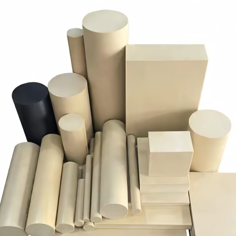
Types Of Materials Suitable For Turning
In turning, choosing the right cutting parameters is a key step in determining product quality and processing efficiency. Whether you are dealing with high-strength titanium alloys or soft, easily fusible plastics, there are clear technical standards for cutting speeds, feed rates and cutting depths for different materials . If the parameters are not set properly, it will not only cause the surface roughness to exceed the standard and the size to be out of control, but also increase tool wear and even damage the equipment.
Table of recommended turning parameters for metal materials
| Material Type | Cutting speed Vc (m/min) | Feed rate f (mm/rev) | Cutting depth ap (mm) | Processing suggestions |
| Aluminum Alloy | 200–400 | 0.15–0.35 | 0.5–3.0 | Soft material, smooth chip removal, suitable for high-speed rough machining and smooth surface finishing |
| Carbon Steel | 100–180 | 0.1–0.3 | 0.5–2.0 | Conventional materials, pay attention to tool wear and cooling control |
| Stainless steel | 60–120 | 0.08–0.2 | 0.3–1.5 | Severe work hardening requires the use of sharp tools and lower speeds to control temperature rise |
| Titanium Alloy | 30–70 | 0.05–0.15 | 0.2–1.0 | Difficult to machine materials, requiring small cutting depth + strong cooling system to prevent tool breakage |
Recommended Turning Parameters For Plastics And Composite Materials
| Material Type | Cutting speed Vc (m/min) | Feed rate f (mm/rev) | Cutting depth ap (mm) | Processing suggestions |
| ABS,POM | 150–250 | 0.2–0.4 | 0.5–3.0 | Good cutting performance, easy chip removal, use sharp tools to avoid edge melting |
| Nylon (PA) | 100–200 | 0.2–0.35 | 0.5–2.5 | Easy to deform, sufficient cooling and margin are required |
| PTFE, PEEK | 80–150 | 0.1–0.25 | 0.3–1.5 | Low rigidity material, easy to burr, need low speed finishing |
| Carbon fiber/glass fiber composite materials | 50–100 | 0.05–0.15 | 0.2–0.8 | Large wear, diamond tools are recommended, and the surface layer is mostly processed by “semi-finishing turning + grinding” |
Advantages And Limitations Of Turning Technology
In my many years of practical processing experience, turning technology has always been one of the most core and commonly used technologies in precision manufacturing. Its advantage is that it can quickly achieve high-precision and high-repeatability processing goals. However, turning is not a panacea . It is more suitable for rotating body structures, but it is powerless for special-shaped parts or large flat parts. At the same time, the continuous cutting process causes rapid wear of the tool, and there are more metal chips during the processing, which also means that the material utilization rate is low. Understanding these advantages and limitations can help us choose turning or other alternative processes more scientifically when designing and formulating processes.
The following is a comparison table of the advantages and disadvantages of turning processes:
| project | Advantages | Limitations |
| Processing accuracy | Up to ±0.005mm, suitable for high precision requirements | Limited support for non-rotating structures |
| Processing efficiency | CNC system + automatic tool change, can realize batch continuous processing | The tool wears quickly and needs to be replaced frequently |
| Production cycle | Flexible programming, fast machine operation, suitable for rapid prototyping and small batch manufacturing | The processing of oversized or complex structures is not as flexible as milling |
| Material adaptability | Can process most metals and some engineering plastics | The cutting parameters need to be adjusted according to the material to control the tool life and surface quality |
| Cost Control | Low cost and easy adjustment in small batches | There is a lot of processing waste, especially in the rough processing stage, the material utilization rate is low |
Common Problems And Solutions In Turning
In the actual processing process, turning operations often encounter problems such as tool chattering, dimensional instability, excessive surface roughness, and chip entanglement . If not handled in time, it will not only affect the quality of the parts, but may also damage the tool or even the machine tool.
As a CNC engineer, I have summarized my experience in solving problems on the front line over the years. From the three dimensions of problem manifestation, cause analysis, and response strategy , I have systematically sorted out the following common problems and solutions :
| Question Type | Typical manifestations | Possible causes | How to deal with it |
| Size out of tolerance | The processing size is too large or too small, exceeding the tolerance zone | Workpiece thermal deformation, tool wear, coordinate offset | Use tool compensation/coordinate offset compensation; regularly change tools; control cooling before and after processing |
| Poor surface roughness | There are vibration marks, scratches and burrs on the surface | Tool passivation, unreasonable cutting parameters, hard spots in the material | Change tool; reduce feed rate; optimize cutting speed; use finishing parameters |
| Blade vibration | The tool vibrates and the workpiece surface has obvious ripples | The tool bar extends too long, the clamping force is insufficient, and the workpiece overhang is too long | Shorten tool overhang; strengthen clamping; increase tailstock support |
| Chip entanglement | Chips wrap around the workpiece or tool, affecting processing or causing surface scratches | The material has high plasticity, the chips are not easy to break, and there is no chip breaker groove | Use chipbreaker tools; increase interrupted cutting; use coolant to assist chip removal |
| Fast tool wear | Short use time, severe wear on the blade tip | Cutting speed is too high, material hardness is high, cooling is insufficient | Reduce cutting speed; change blade material suitable for the material; optimize cooling method |
| Tool chipping | The tool breaks or collapses suddenly | The processing parameters are set too radically, the feed speed is unstable, and there are inclusions in the material. | Reduce feed rate; improve feed trajectory smoothness; change tool material |
| Large fluctuations in workpiece size | The size deviation of workpieces in the same batch is large | Poor thermal expansion control, program errors, clamping deformation | Thermal stabilization before each batch of processing; program verification; fixture optimization |
| Cutting heat is too high | The workpiece becomes hot, the dimensions are unstable, and the surface changes color | Insufficient coolant, tool wear, excessive cutting parameters | Increase coolant flow; check tool condition; reduce cutting depth and speed |
Through the analysis and continuous optimization of the above problems, I have effectively improved the yield rate and tool life in turning. If you encounter similar problems, you can refer to the above table for quick diagnosis and response to ensure a smooth and efficient production process.
FAQs
What Is The Process Of Facing And Turning
Facing And Turning Are Two Fundamental Lathe Operations I Use To Shape And Finish Cylindrical Parts. In Facing, I Move The Cutting Tool Perpendicularly To The Workpiece Axis To Create A Flat Surface—Usually The First Step. On A CNC Lathe, I Often Combine Both Steps In One Program To Achieve Precision Within ±0.01mm.
What Is The Purpose Of Facing Operation
The Main Purpose Of A Facing Operation, In My Work, Is To Produce A Perfectly Flat And Perpendicular Surface At The End Of A Workpiece. This Ensures Accurate Length Reference And Proper Seating For Assembly. I typically Perform Facing First To Eliminate Material Irregularities And Prepare The Part For Further Machining, Achieving Surface Roughness As Low As Ra 0.8μm.
How Does A Boring Operation Differ From A Turning Operation
Boring And Turning May Look Similar But Serve Different Purposes. In Turning, I Cut The Outer Diameter Of A Workpiece; In Boring, I Enlarge Or Finish An Existing Internal Hole. Boring Requires Greater Rigidity And Often Uses A Single-Point Boring Bar. I Use Boring For Internal Tolerances Within ±0.01mm, Especially On Deep Or Precision Holes.
What Does Turning Mean In Machining
Turning In Machining Refers To The Process Where I Rotate A Workpiece While A Single-Point Tool Removes Material To Form Cylindrical Shapes. This Operation Is Done On A Lathe, And It’s Core To Creating Shafts, Bushings, Or Housings. With Proper Parameters—Like 100–300m/min Cutting Speed—I Can Reach Tolerances Of ±0.005mm On Steel Or Aluminum Parts.
Conclusion
Although the turning process seems to be standardized and highly automated, behind each process lies the ultimate control of experience and details. Common problems such as vibration, dimensional deviation, surface roughness, chip entanglement, etc. are often the result of multiple factors, and must be analyzed and adjusted from multiple dimensions such as equipment, tools, parameters, cooling, and tooling . For me, turning is not just “removing material”, but a continuous game of precision, efficiency, and stability. Only by continuously optimizing every detail can we ensure high-quality and highly consistent processing output. If you are also on the road to improving turning quality, I believe this list of problems and solutions will become one of the practical tools in your workshop.