Achieving tight tolerance in CNC machining is all about controlling the smallest possible deviations—from tool deflection to thermal shifts, everything counts.I’ll walk you through how I approach tight tolerance projects in my daily work. Whether you’re making aerospace components or medical implants, tight tolerance CNC machining demands careful planning, the right tools, environmental control, and quality inspection.
What Are Machining Tolerances
Machining tolerance defines how much a manufactured part may deviate from its nominal design size. It is essential for achieving proper fit, functional reliability, and long-term performance. Knowing tolerance types, standards, and material capabilities helps engineers make informed, cost-effective manufacturing decisions.
What Is Considered A Tight Tolerance In CNC
Tight Tolerance Ranges for Metals
Standard tight tolerance: ±0.01 mm
High precision: ±0.005 mm
Aerospace/medical grade: ±0.002–0.003 mm
Ultra-precision: ±0.001 mm
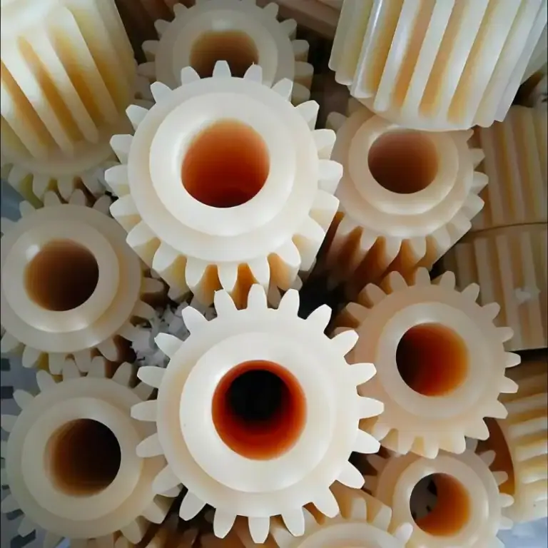
Tight Tolerance Ranges for Plastics
Due to thermal expansion and flexibility:
General tight tolerance: ±0.02–0.05 mm
Engineering plastics (PEEK/POM): up to ±0.01 mm
Example: A PEEK housing for a medical sensor required ±0.01 mm to fit micro-electronics properly.
Micro-Manufacturing Tolerances
CNC micro machining: ±0.002–0.005 mm
Micro EDM: ±0.001 mm
Ultrafast laser machining: ~1 µm
Engineering Standards & Tolerance Grades
ISO 2768 Tolerance Classes
f – Fine: precision metal machining
m – Medium: standard CNC machining (TiRapid default)
c – Coarse: welded and structural parts
v – Very coarse: rough or pre-machined parts
IT Grades and Tight Tolerance
IT6–IT7 = Tight tolerance (±0.006–0.01 mm)
IT8–IT10 = Normal precision
IT11–IT13 = General machining
Material-Based Tolerance Capability
Aluminum, brass → Best for ultra-tight tolerances
Stainless steel, titanium → More heat-affected, harder to machine
Plastics → Higher thermal movement, wider tolerance recommended
Example: A PTFE valve body required tolerance relaxation from ±0.01 mm to ±0.03 mm to improve manufacturability.
Why Tight-Tolerance CNC Machining Matters
Better Fit and Functional Reliability
Tight tolerances ensure smooth assembly and prevent vibration, binding, or excessive wear.
Consistency Across Mass Production
They ensure:
Repeatability
Reduced scrap
Stable quality
Safety, Compliance & Certification Requirements
Industries like aerospace and medical devices demand stable tolerance control to meet AS9100, ISO 9001, and other standards.
Longer Lifespan and Equipment Reliability
Precision reduces friction and thermal distortion, extending component life and improving system stability.
What Are The Key Factors For Achieving Tight Tolerance Precision
Achieving tight tolerances is the result of optimized design decisions, material behavior control, machine capabilities, workholding, cutting tools, shop environment, and advanced inspection systems. When these factors work together, manufacturers can deliver consistent accuracy, reduce scrap, and balance quality with cost efficiency.
Process Planning & Design
Tight tolerances must be defined correctly from the design stage, not forced later during machining.
Define tolerance ranges rationally
Many customers initially request ±0.01mm or even ±0.005mm, though the function doesn’t require such precision.
In a PTFE valve I handled, we suggested relaxing ±0.01mm to ±0.03mm through DFM. Throughput increased by 30%, and cost dropped by about 20%.
Avoid over-precision
Over-tight tolerances dramatically increase tool wear, machining time, setup cost, and inspection time. Precision cost grows exponentially the tighter the tolerance becomes. Therefore, only critical features should receive strict control.
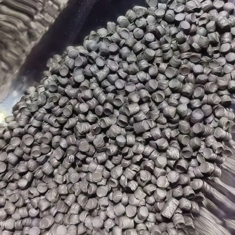
Material Factors
Different material properties directly determine the achievable tolerance range.
Plastics: high thermal expansion & easy deformation
Materials like PEEK, POM, and PTFE have high thermal expansion coefficients. After machining, their dimensions may drift.
For example, a POM part moved from a 20°C shop to a 35°C area may change by more than 0.02mm.
Aluminum alloys: stable and suitable for tight tolerance work
6061 and 7075 machine extremely well and commonly achieve ±0.01mm or tighter with stable consistency.
Stainless steel & titanium: hard materials cause tool deflection
Materials such as 304, 316, and Ti6Al4V harden during cutting and generate high tool loads, leading to cutting-edge deflection. Smaller step-downs and harder tool materials are required to maintain precision.
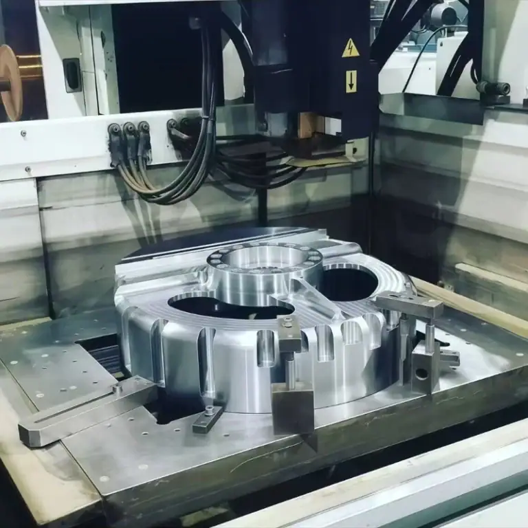
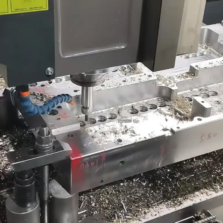
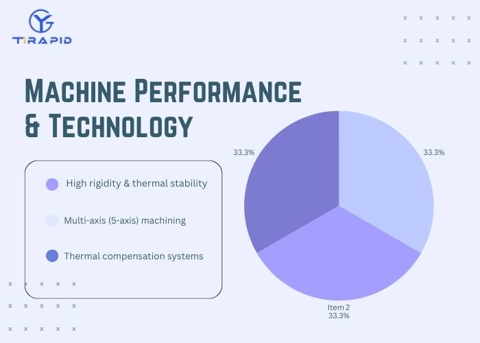
Machine Performance & Technology
High-precision machines are the foundation of achieving tight tolerances.
High rigidity & thermal stability
Tight tolerance parts often rely on high-end machines (e.g., Makino, DMG MORI), whose structures minimize deformation during load.
Multi-axis (5-axis) machining
5-axis capability reduces secondary setups and eliminates accumulated errors.
In an aerospace aluminum project, switching from three setups to one 5-axis operation kept tolerance within ±0.008mm consistently.
Thermal compensation systems
Advanced machines include real-time thermal growth compensation to stabilize spindle elongation and maintain micron-level accuracy.
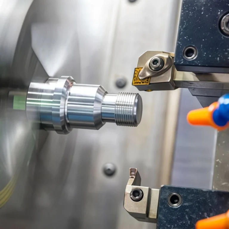
Workholding & Cutting Tools
High-precision fixtures
Fixturing repeatability must be within ±0.005mm. For high-tolerance parts, vacuum fixtures or custom tooling fixtures are often required.
Tool material & geometry selection
Carbide tools, coated tools, and tools with micro-radius edges reduce cutting forces and tool deflection.
Shrink-fit holders help control runout below 2μm, significantly improving surface finish and tolerance accuracy.
Machining Environment Control
Temperature control within ±1°C
Metals expand with temperature. For example, steel may change by 10μm for every 10°C increase. Thus precision machining shops must use air-conditioning and constant-temperature systems.
Minimize vibration, dust, and humidity
Vibration causes runout, chatter marks, and dimensional drift.
I’ve visited machine shops located on upper floors where building vibration caused tolerance deviations above 0.02mm.
Inspection & Measurement Technology
On-machine probing systems
Systems like Renishaw probes correct tool offsets during machining, reducing process-induced deviations and ensuring stable accuracy.
High-precision metrology equipment
CMMs, laser interferometers, and white-light interferometers are essential to achieve micron-level measurement.
For a ±0.005mm valve project we produced, full inspection plus temperature-controlled measurement was required to ensure consistency across all parts.
How To Apply DFM For Tight-Tolerance CNC Machining
In precision machining, the design phase determines more than 80% of the final manufacturing cost, lead time, and yield. Tight tolerances are not always beneficial. Without DFM, they increase machining hours, tool wear, and scrap rates.
When Do You Truly Need Tight Tolerances
Tight tolerances must be driven by functional needs, not by “tightening everything by default.”
Avoid over-designing with tight tolerances everywhere
Many drawings we receive mark almost all features at ±0.01mm, though only 3–5 surfaces actually need this precision.
In an aerospace aluminum housing project, relaxing twenty ±0.01mm dimensions to ±0.03mm reduced machining time by ~40% and lowered scrap from 12% to 2%.
Impact of tight tolerances on cost, lead time, and yield
Tight tolerances significantly increase manufacturing difficulty:
Machining time rises by 30–200%
Inspection effort doubles
Tool life drops by over 50%
Scrap rate increases, especially for plastics and thin-wall parts
Therefore, tight tolerances should only be applied to surfaces affecting fit, sealing, safety, or motion accuracy.
Setting The Correct Tolerances & Fit Classes
Engineering design must balance manufacturability and functional intent.
Select practical fit classes and use GD&T correctly
Common fit pairs include H7/g6 and H8/f7.
Over-tight fits do not improve function—they only raise cost.
GD&T symbols like Position, Coaxiality, and Profile represent functional requirements more accurately than extremely tight linear tolerances.
Avoid conflicting or overly restrictive tolerance chains
For example, specifying both very tight bilateral tolerances and an extremely strict position tolerance on the same hole may create impossible requirements.
Tolerance chains must be derived from assembly baselines, ensuring every tolerance is necessary and achievable.
Tolerance stack-up & assembly tolerance planning
Final assembly variation is the sum of individual part variations.
In a stainless-steel medical guide sleeve project, the assembly allowed only 0.04mm total variation.
We allocated ±0.01mm to critical parts and ±0.05mm to non-critical parts, achieving the assembly target with minimal cost.
Key Geometric Design Principles For Achieving Tight Tolerances
The geometry of a part directly determines how feasible the required tolerance will be.
Use fillets instead of sharp internal corners
A perfect internal zero-radius corner cannot be machined.
Recommended internal fillet: ≥1.5× tool radius (commonly 0.5–1mm).
This reduces tool load, vibration, and improves dimensional stability.
Rational design of walls, steps, threads, grooves, and chamfers
Wall thickness ≥0.8mm (≥1.2mm for plastics) to avoid deformation
Groove width ≥1.3× tool diameter for manufacturability
Thread depth ≤2× thread diameter to avoid tool breakage and tolerance failure
Consistent chamfers improve repeatability and assembly quality
Relationship between surface roughness and dimensional tolerance
Finer Ra dramatically increases cost.
For example, Ra0.4μm can cost 2–3× more than Ra0.8μm.
In an aerospace aluminum part, relaxing Ra0.4μm to Ra0.8μm while keeping ±0.01mm tolerance reduced unit cost by ~25%.
Methods & Best Practices For Achieving Tight-Tolerance CNC Machining
Achieving tight tolerances requires more than a single factor. It depends on material behavior, machine capability, process planning, tooling, and quality control. Through better workshop management, optimized cutting parameters, refined workflows, and precise inspection, manufacturers can reliably reach ±0.01mm or even ±0.005mm tolerances while reducing scrap and overall cost.
Foundational Workshop Management
Choosing the right machining facility/production environment
Precision machining requires stable facility conditions, such as: Ground-floor workshops or vibration-isolated foundations
High-performance machines (Mazak, DMG MORI) ensuring spindle runout ≤2μm
One customer attempted to machine ±0.01mm parts on a second-floor workshop and saw variations up to ±0.03mm due to floor vibration. After transferring production to our facility, all dimensions stabilized.
Stable workshop temperature and clean production environment
Temperature strongly affects dimensions. For example:
Aluminum expands≈0.023mm/m per 1°C
Steel≈0.011mm/m per 1°C
Maintaining temperature within ±1°C is essential for dimensional consistency.
Dust and oil mist can also affect guideways and tool-holder repeatability.
Using high-quality CNC machines and regular calibration
Key measures include:
Spindle calibration via laser interferometer (positioning error≤2μm)
Ballbar testing to compensate machine geometry
Pull-force verification of tool holders
Proper machine maintenance reduces dimensional drift from ±0.02mm to ±0.005mm.
Tooling & Cutting Parameter Optimization
Selecting proper and sharp tools for each material
Aluminum: high-speed steel or carbide
Stainless steel/Titanium: coated tools (TiAlN, AlTiN)
Plastics like PTFE require sharp edges to avoid deformation
Sharp tools reduce cutting forces and improve tolerance stability by 20–40%.
Balancing cutting speed, feed rate, and depth of cut
Typical values:
Aluminum: 12000rpm, 1800mm/min feed, 0.3mm DOC
Stainless steel: 3500rpm, 400mm/min feed, 0.1mm DOC
Incorrect feed or cutting speed causes chatter, heat buildup, and dimensional error.
Tool wear monitoring & replacement strategy
Inspect cutting edges every 20–40 parts
Use tool-life management software
For ±0.005mm tolerance parts, replace tools every critical step
This strategy reduced scrap from 6% to under 1% for a copper-part project.
Process Planning: Roughing → Semi-Finishing → Finishing
Dividing machining steps
Roughing removes 60–80% material
Semi-finishing leaves 0.2–0.4mm stock
Finishing achieves final dimension in one pass for maximum accuracy
Strict process division reduces dimensional variation by over 50%.
Raw stock selection & machining allowance planning
Too large stock increases cycle time, too small stock causes clamping instability.
For ±0.01mm parts, at least 3mm additional stock is recommended for secure clamping.
High-volume vs low-volume/prototype strategies
Mass production: cycle repeatability, tool-life management, in-process measurement
Prototypes: flexibility and single-part optimization
We often use dedicated fixtures for mass production and soft jaws for prototypes.
In-Process & Final Inspection
On-machine probing & closed-loop compensation
Using Renishaw probes allows:
In-process measurement of critical dimensions
Automatic tool length and diameter compensation
Prevention of heat-drift-induced tolerance failure
Mandatory for parts requiring ±0.005mm.
First Article Inspection (FAI) & sampling plans
100% dimensional inspection for FAI
Sampling every 10–30 parts during production
SPC charts for monitoring key dimensions
Reducing scrap through early inspection
By implementing FAI + in-process probing on a medical part project, we reduced scrap from 8% to 1.5%.
How To Balance Cost And Risk In Tight Tolerance Machining
In precision manufacturing, the tighter the tolerance, the higher the cost, difficulty, and risk. Companies must balance performance, budget, lead time, and manufacturability. Unnecessarily specifying ±0.005mm tolerances can cause excessive costs, longer production cycles, and higher scrap rates.
Why Do Tighter Tolerances Increase Cost
The cost rise in tight tolerance machining comes from multiple combined factors:
More machining steps are required
Achieving ±0.01mm or ±0.005mm typically demands multiple stages such as roughing → semi-finishing → finishing → compensation passes.
For example, in a stainless steel bracket we produced, achieving a ±0.008mm bore required two additional fine-cut passes, doubling machining time.
Feed rates must be significantly reduced
Slower, more stable cutting prevents heat-induced dimensional drift.
During aluminum machining, we reduced feed rate from 1200mm/min to 450mm/min to maintain ±0.01mm flatness—substantially increasing cycle time.
Specialized tooling and fixtures are required
Micro-level tolerances often require PCD tools, custom boring bars, or ultra-hard cutters, costing 3–8× more than standard tools and wearing faster.
Higher scrap and rework risk
With a ±0.005mm window, the allowable range is extremely narrow. Even a 0.002mm deviation can make a part unusable, especially with difficult materials like titanium or stainless steel.
Cost structure for precision projects
Tight tolerance machining affects quotations due to:
Longer machining cycles (2–5× compared to standard tolerances)
Faster tool wear
Longer inspection time with CMM or laser measurement
Lower yield rate
This is why tightening tolerances from ±0.05mm to ±0.01mm may increase the cost by 30%–200%.
Balancing Performance And Manufacturability
In DFM, tighter tolerance does not mean“the tighter, the better”—it means“tight enough for function.”
Discussing an appropriate tolerance level with your supplier
Experienced machining partners can recommend tolerances based on function and manufacturability.
For example, in a PEEK housing we made, the customer initially requested ±0.01mm. After evaluating functional requirements, we adjusted to ±0.03mm, reducing cost by 40% and cutting lead time in half.
Where can tolerances be relaxed
Tolerances can typically be loosened in:
Non-mating surfaces
Exterior cosmetic areas
Regions not affecting assembly alignment
Features not sensitive to wall thickness
A customer once specified ±0.02mm across an entire aluminum bracket. Only three holes were critical. By relaxing other features to ±0.1mm, productivity improved nearly threefold.
Strategies to optimize tolerances without affecting performance
Replace sharp corners with fillets
Increase wall thickness to reduce deformation
Adjust surface finish from Ra0.8 to Ra1.6 to save machining time
Use tolerance stack-up analysis to avoid redundant precision cuts
Smart tolerance setting ensures both performance and cost efficiency.
What Are The Typical Applications & Industry Standards
Tight-tolerance CNC machining is essential in medical, aerospace, semiconductor, automotive, and high-precision industrial applications. These sectors demand exceptional dimensional accuracy, reliability, and functional stability.
| Application Industry | Typical Tight-Tolerance Parts | Tolerance Requirements |
| Medical Devices & Dental Implants | Surgical tools, implant connectors, micro valve bodies, corrosion-resistant supports | Commonly ±0.01mm to ±0.005mm, high surface quality and repeatability required |
| Aerospace & Defense Components | Turbine parts, actuators, structural links, precision mounts | Extremely high reliability, some critical areas require ±0.005mm or tighter |
| Electronics & Semiconductor Fixtures | Wafer chucks, heat dissipation modules, precision jigs, ceramic insulators | High dimensional stability, strict flatness and surface finish requirements |
| Automotive & New Energy Systems | Motor housings, sensor seats, fluid control valves, battery structural parts | High consistency in mass production, typically ±0.02mm to ±0.01mm |
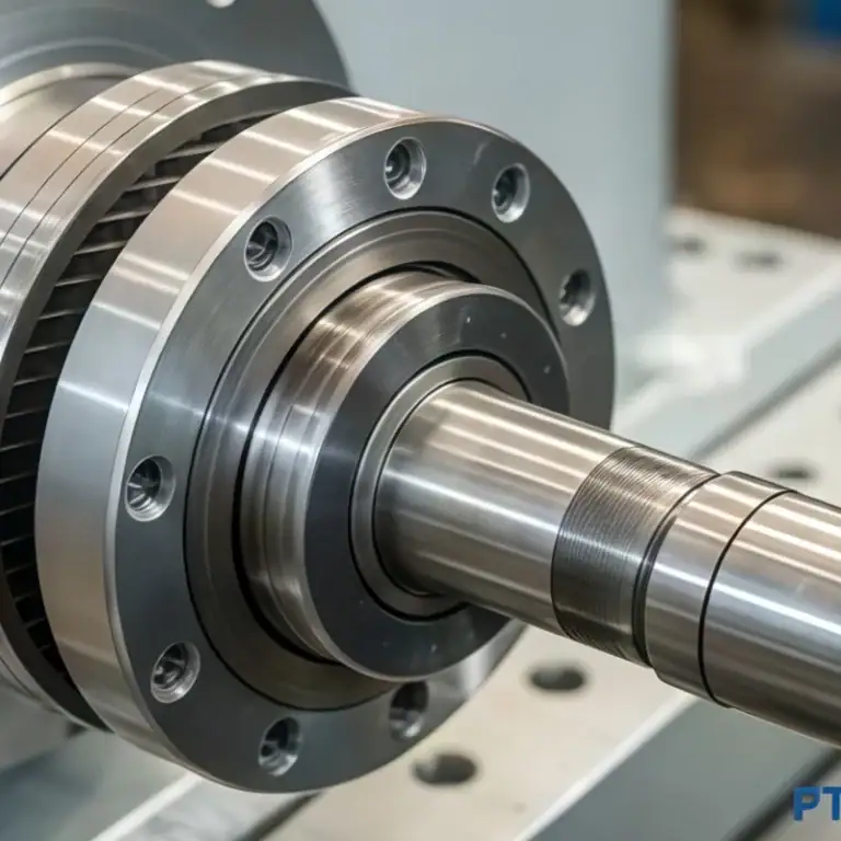
| High-Precision Industrial & Instrumentation Parts | Metrology components, hydraulic/pneumatic parts, precision shafts and bushings | Strict control of wear resistance, coaxiality, and perpendicularity, ±0.01mm or below |
FAQs
What Is The Highest Tolerance For Machining?
In general CNC machining, the highest (i.e., loosest) tolerance I work with is ±0.1 mm, common for structural or non-critical components. For example, brackets or covers that don’t require tight fits. This level keeps production fast and cost-effective, especially for large parts where dimensional variation is acceptable.
Which Tolerance Is Most Difficult To Machine?
Tolerances tighter than ±0.002 mm (2 microns) are extremely challenging. At that level, even minor thermal shifts, tool wear, or material inconsistencies can push a part out of spec. I usually rely on ultra-stable 5-axis machines, CMM checks, and temperature-controlled environments to meet such demands.
What Is The Minimum Tolerance For Machining?
The minimum tolerance I’ve successfully achieved in real production is ±0.001 mm (1 micron), typically through high-end micro-EDM or femtosecond laser machining. For conventional CNC, the limit is around ±0.002–0.005 mm depending on the setup, material, and inspection method.
What Are The Tolerance Grades For Machining?
I use ISO 2768 for general machining—graded into Fine (f), Medium (m), Coarse (c), and Very Coarse (v). For precision work, GD&T allows me to apply form and location controls within ±0.01 mm or tighter. In aerospace, AS9100 standards often push tolerances to ±0.005 mm or better.
What Happens When Manufacturing Tolerances Are Too Tight?
When tolerances are too tight—say, below ±0.005 mm unnecessarily—I often see a 2–3× increase in machining time, more frequent tool changes, and scrap rates that can exceed 15%. It also demands higher inspection costs and stricter environmental control. Unless functionally required, such tolerances reduce efficiency and drive up per-unit costs significantly.
Conclusion
Tight tolerance machining in CNC is a blend of precision science and manufacturing art. From my experience, success depends on one thing above all: discipline. Discipline in design, process control, measurement, and communication. Whether you’re pushing for ±0.002 mm or simply trying to meet aerospace specs, the secret is in controlling everything you can—and knowing what you can’t.
Tight tolerance isn’t about perfection—it’s about consistency, communication, and smart decisions. If you’re tackling a challenging part or trying to improve your process, don’t hesitate to reach out or share your situation. Sometimes, a second opinion makes all the difference.