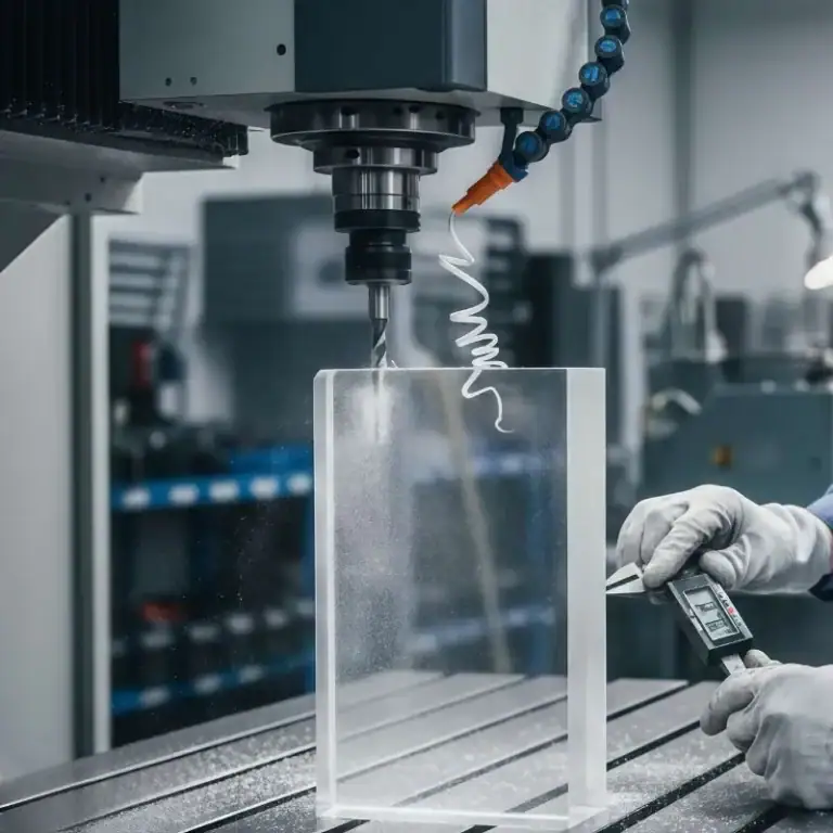
In product design, even the smallest edge detail can influence strength, assembly, safety, and machining cost. When comparing Fillet vs Chamfer, these two edge treatments serve very different functions. Fillets provide smooth curved transitions that improve stress distribution, while chamfers add angled surfaces that simplify assembly and reduce sharp edges. Understanding how each option affects performance, appearance, and manufacturability is essential for choosing the right edge in CNC machined parts.
What Is a Fillet
A fillet is a rounded transition between two surfaces, commonly used in CNC machining, product design, and engineering to eliminate sharp corners. By replacing a sharp edge with a smooth curve, fillets significantly reduce stress concentration, improve part durability, and enhance overall safety and appearance.
What Is a Chamfer
A chamfer is a flat, angled edge created by cutting away the sharp corner between two surfaces. Unlike a fillet’s curved transition, a chamfer uses a straight, beveled slope—commonly 45°—to make assembly easier, remove sharp edges, and improve manufacturability in CNC machining.
Key Differences Between Fillets and Chamfers
Fillets and chamfers may look like simple edge modifications, but their impact on manufacturability, stress resistance, cost, and part performance is substantial. Understanding their core differences helps engineers choose the right edge type for strength, safety, and machining efficiency.
Shape and Geometry
A fillet creates a smooth, rounded transition, while a chamfer produces a straight, angled cut. Fillets distribute stress evenly, whereas chamfers break sharp edges without altering stress flow significantly.
Stress Distribution & Structural Behavior
Fillets reduce stress concentration by spreading load across a curved radius. Chamfers concentrate stress along a line, making them suitable for designs that require precise edges but not heavy load-bearing.
Machining Cost & Tooling Requirements
Fillets require radius-specific tools (ball-end mills / corner-rounding cutters), increasing machining time and cost. Chamfers are cheaper because a single chamfer tool can create different sizes.
Safety & Handling
Fillets eliminate sharp edges, making parts safer to handle. Chamfers still create defined edges that may remain sharp if not deburred properly.
Machining Speed
Fillets take longer due to multi-axis toolpaths with small stepovers. Chamfers are faster to manufacture because the angled cut is simpler and more direct.
Application Scenarios
Fillets are ideal for high-stress locations, load-bearing parts, castings, and smooth fluid/air transitions.
Chamfers are preferred for assembly alignment, hole deburring, and cost-effective edge breaking.
Fillets offer superior stress reduction and smoother transitions, while chamfers provide faster machining, lower cost, and easier assembly alignment. Choosing the right edge depends on strength requirements, manufacturability, and part functionality.
Types of Fillets and Chamfers
Fillets and chamfers come in multiple forms, each offering different mechanical, aesthetic, and manufacturing advantages. Choosing the right type depends on stress distribution, assembly needs, machining cost, and how the part interacts with surrounding components.
Fillet Types
Concave Fillet
A concave fillet creates an inward-curved transition, commonly applied to interior corners of CNC-machined parts. It greatly reduces stress concentration, improves fatigue life, and supports uniform load distribution. In aerospace brackets or automotive housings we produce, a 2–3 mm concave fillet often prevents cracking under repeated vibration.
Convex Fillet
A convex fillet forms an outward-rounded edge, typically used on exterior corners to remove sharp edges and improve handling safety. It also reduces turbulence in fluid-flow components. TiRapid often applies convex fillets on pump housings and aluminum manifolds to enhance both durability and ergonomics.
Miter Fillet
A miter fillet blends two surfaces with a smooth curve meeting at an angled intersection. It’s common in molded and cast parts where material flow needs to be optimized. This type offers aesthetic benefits and reduces tool wear during machining.
Chamfer Types
45-Degree Chamfer
The most widely used chamfer, ideal for deburring, assembly alignment, and screw lead-ins. A 45° chamfer is cost-effective and easy to machine with a single tool. In metal housings, a 0.5–1 mm chamfer prevents edge damage and improves safety.
30° / 60° Functional Chamfers
These chamfers are used when specific lead-in geometry is required, such as fastener seating or guiding mating parts. A 60° chamfer is common for countersinks, while 30° reduces friction during sliding mechanisms.
Symmetric & Asymmetric Chamfers
Symmetric chamfers are used for uniform stress flow. Asymmetric chamfers allow designers to tune force direction, assembly paths, or aesthetics. This is frequently applied in robotics and precision jigs where directional force matters.
Recessed (Hole) Chamfer
Applied to drilled holes to help screws sit flush or to remove burrs. It improves assembly quality and prevents thread damage during installation.
CNC Machining Considerations
When designing fillets or chamfers for CNC machining, tool selection, material behavior, tolerances, and finishing all affect cost and quality. Fillets often need ball-nose tools and multi-axis paths, while chamfers can be cut with simple chamfer mills. Understanding tool geometry and material limits helps engineers choose the most efficient edge.

Key Factors to Consider
Tooling
Fillets require specialized radius cutters or ball end mills, while chamfers use simple 45°/60° chamfer mills. Smaller radii increase machining time due to reduced step-over (typically 0.1–0.2 mm per pass).
Material Compatibility
Hard materials (like stainless steel or titanium) slow down cutter feed rates and require stronger tooling. Softer materials (aluminum, plastics) allow faster machining and smoother edges.
Tolerances
Tight tolerances (±0.02 mm or below) increase cost because they require slower speeds, stable fixturing, and additional inspection. For non-critical edges, standard tolerances reduce cost significantly.
Finishing Requirements
Post-processing such as deburring, polishing, anodizing, or bead blasting can affect the final edge quality. Fillets generally retain smoother finishes, while chamfers offer crisp, clean transitions.
How to Choose the Right Edge
Choosing between a fillet and a chamfer is more than a visual preference—it directly affects strength, machinability, cost, and long-term durability. The right edge design improves stress distribution, eases assembly, prevents premature wear, and reduces manufacturing complexity. By evaluating function, load, cost targets, and machining limitations, engineers can select the edge type that best supports performance and manufacturability.
| Decision Factor | Choose Fillet When… | Choose Chamfer When… |
| Stress Distribution | You need to reduce stress concentration, improve structural strength, or prevent crack initiation. | Stress is acceptable or intentionally concentrated in specific areas. |
| Machining Time | Complex geometry allows for 3D toolpaths; CNC machining time is not a major constraint. | You need faster machining and simpler toolpaths. |
| Cost Efficiency | Budget allows for extra machining time and radius tools. | You need a more cost-effective edge break with minimal tooling changes. |
| Aesthetic Appeal | The design requires a smooth, refined, high-end appearance (consumer products, enclosures, industrial design). | Function is more important than appearance, and a clean beveled edge is sufficient. |
| Rust & Coating Performance | Better coating adhesion is required; fillets help paint/powder coat spread evenly and reduce rust risk. | Coating thickness is not critical, or the part is not exposed to corrosive environments. |
| Assembly Requirements | Smooth transitions are required between mating surfaces or sliding parts. | The design requires lead-ins for screws, bolts, pins, or hole entry. |
| Safety & Handling | Sharp edges must be avoided to protect users or operators. | Handling safety is less critical, or the edges will be hidden inside assemblies. |
| Hole Functions | You need smooth transitions around openings, internal curves, or load-bearing corners. | Screws, pins, or bolts need a 45°–60° lead-in; countersinking is required. |
| Material Behavior | The material benefits from reduced stress (e.g., aluminum, plastics, cast metals). | The material can tolerate sharper geometry without deformation. |
| Manufacturing Method | 3D printing, casting, molding, or CNC milling where smooth curved transitions are preferred. | CNC machining, hand-deburring, or drilling operations where straight bevels are easier. |
FAQs
What Is The Difference Between Fillet And Chamfer?
The difference between chamfer and fillet is shape and function. A fillet is a rounded edge used in CNC fillet / fillet CNC to reduce stress concentration and improve strength. A chamfer is a flat angled edge made by chamfer CNC, mainly for deburring and assembly. In chamfer vs fillet, fillets focus on strength, chamfers on manufacturability.
Is A Chamfer Or Fillet Stronger?
A fillet is stronger. In chamfer vs fillet stress concentration analysis, fillets spread load more evenly and reduce peak stress, making them better for fatigue-critical parts. Chamfers are suitable where strength is not critical.
Is A Chamfer Always Cut At 45?
No. While 45° is common in chamfer CNC, chamfers can range from 15° to 60° depending on assembly and fastener design.
When To Use Chamfers?
Use chamfers for easier assembly, edge safety, and lower cost. In chamfer vs fillet decisions, chamfers are preferred when stress reduction is not required.
Are Chamfers Cheaper Than Fillets?
Yes. Chamfers need simple toolpaths, while fillet CNC requires radius tools and longer machining time, increasing cost.
Conclusion
Fillets and chamfers may seem like minor design details, but they have a significant impact on strength, manufacturability, assembly, and cost. Fillets improve stress distribution and durability, while chamfers provide fast edge removal and easier assembly. Choosing the right edge depends on function, load requirements, aesthetics, and machining strategy. By understanding these differences, designers can optimize part performance while controlling production time and cost.