Copper CNC machining may seem straightforward due to copper’s softness, but its high ductility and thermal conductivity lead to unique machining behaviors. From pure copper to free-machining alloys, each material grade performs differently under cutting conditions and requires specific tooling strategies in modern CNC machining manufacturing.
This article explains copper materials, machinability characteristics, machining processes, and industrial applications, helping engineers select the right alloy and process to improve precision, efficiency, and overall cost control.
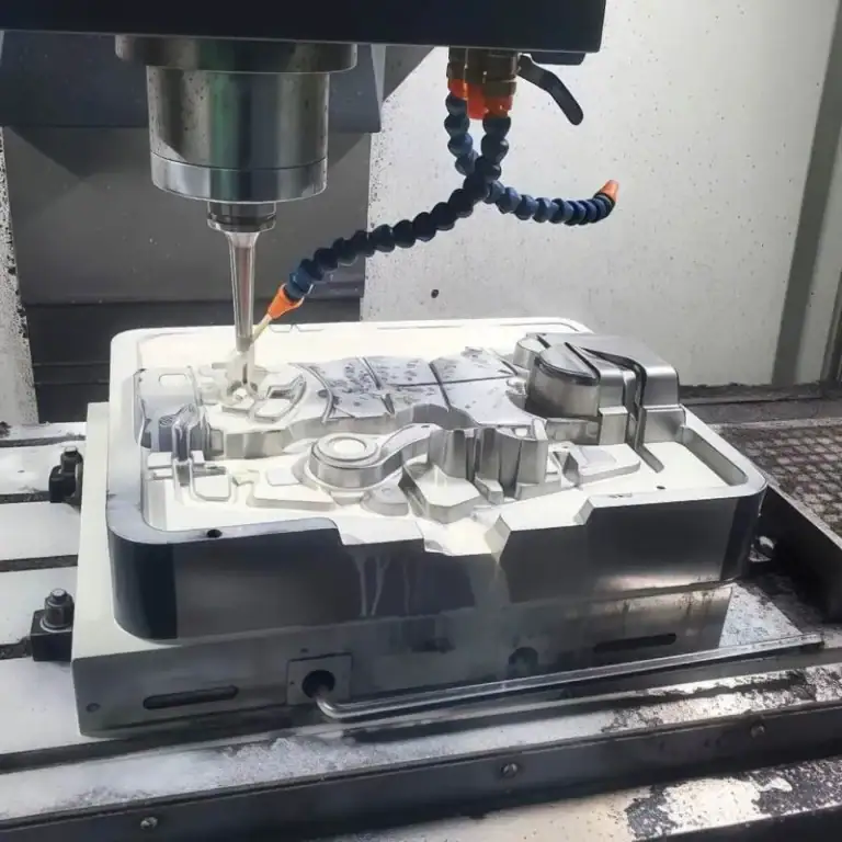
What Are The Main Steps In Copper CNC Machining?
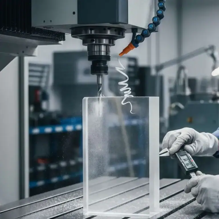
Copper CNC machining typically follows a controlled workflow to ensure dimensional accuracy, surface quality, and stable conductivity performance. Because copper is soft and ductile, each step must focus on chip control, heat management, and burr reduction.
Material Selection And Verification
Material selection is the foundation of copper CNC machining. I first determine the appropriate copper grade—such as C101 for maximum conductivity, C110 for general electrical use, or C14500 for improved machinability—based on performance requirements. I then verify material certification, hardness condition, and dimensional allowance for machining. Because copper is a high-value material, confirming correct grade and stock condition prevents downstream waste and machining instability.
DFM Review And Process Planning
Before machining begins, I conduct a detailed design for manufacturability (DFM) review. This includes evaluating wall thickness, internal radii, deep cavities, tolerance stacking, and surface finish requirements. Based on this assessment, I define datum references, machining sequence, cutting strategy, and whether multi-axis setups are required. Proper process planning reduces setup changes, minimizes tool wear, and improves repeatability across production batches.
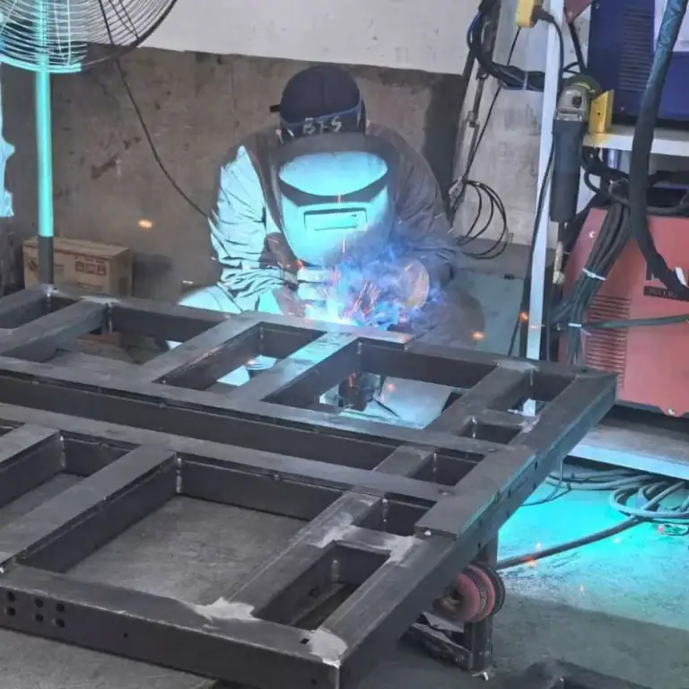
Fixturing And Workholding Setup
Copper’s softness makes it susceptible to clamping deformation. I select rigid yet balanced workholding solutions to minimize vibration while avoiding surface indentation. Proper fixture design ensures stable positioning and consistent dimensional accuracy. For high-precision parts, I may use soft jaws or custom fixtures to protect critical surfaces and maintain positional stability throughout the machining cycle.
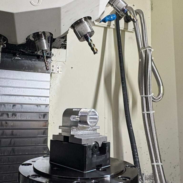
Rough Machining
Rough machining removes the majority of excess material while maintaining structural stability. I control depth of cut and radial engagement to prevent excessive heat buildup or tool deflection. Efficient chip evacuation is critical during this stage, as long continuous chips can interfere with cutting stability. Optimized cutting parameters reduce smearing and extend tool life.
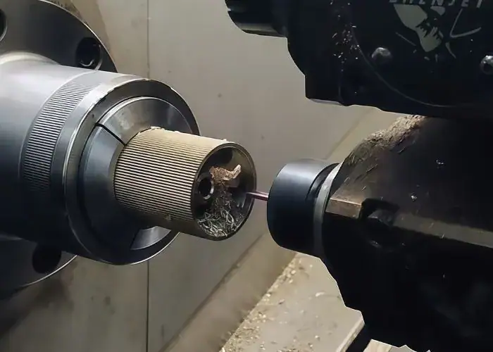
Semi-Finishing And Feature Machining
During semi-finishing, I machine key features such as pockets, slots, drilled holes, and threaded areas. This stage prepares the part for final finishing while refining dimensional accuracy. Burr formation is closely monitored, especially around edges and hole exits. Maintaining consistent tool engagement helps preserve feature-to-feature positional accuracy.
Finishing Pass And Surface Control
Finishing passes are applied to achieve final tolerances and required surface finish levels. I reduce radial engagement and adjust feed rates to minimize tool marks and material tearing. Tool sharpness and polished cutting edges are especially important in copper to prevent edge deformation. Surface finish control is critical for electrical contact and thermal interface components.
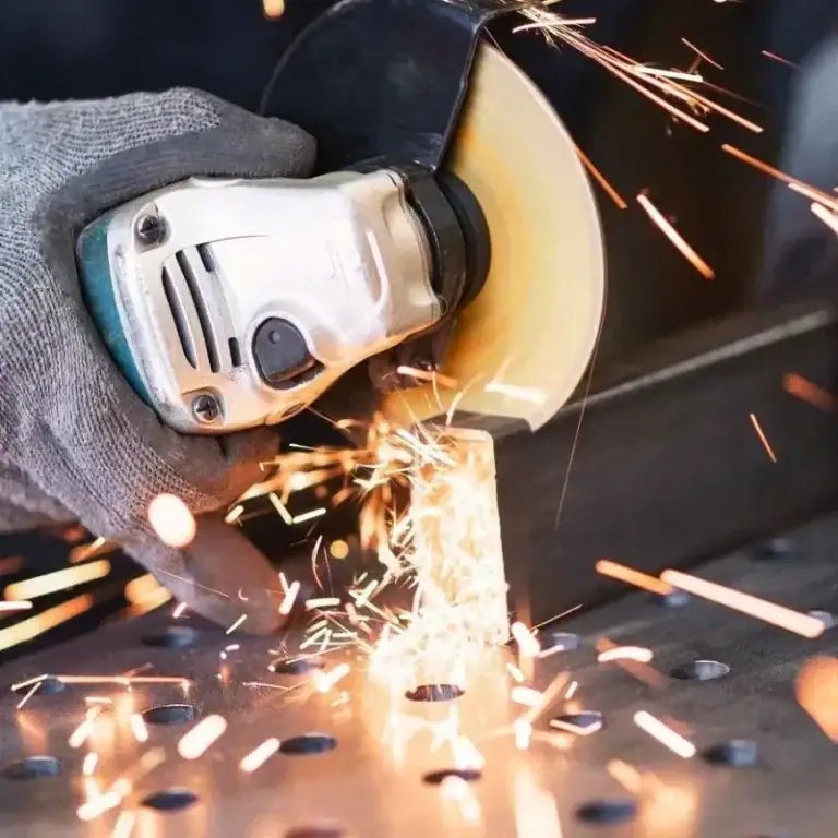
Deburring And Cleaning
Copper machining often produces edge burrs due to material ductility. I remove burrs carefully through mechanical or manual processes to protect functional surfaces. After deburring, parts are cleaned to remove chips, oil residue, and contaminants. Clean surfaces are especially important in electrical and thermal applications to ensure reliable performance.
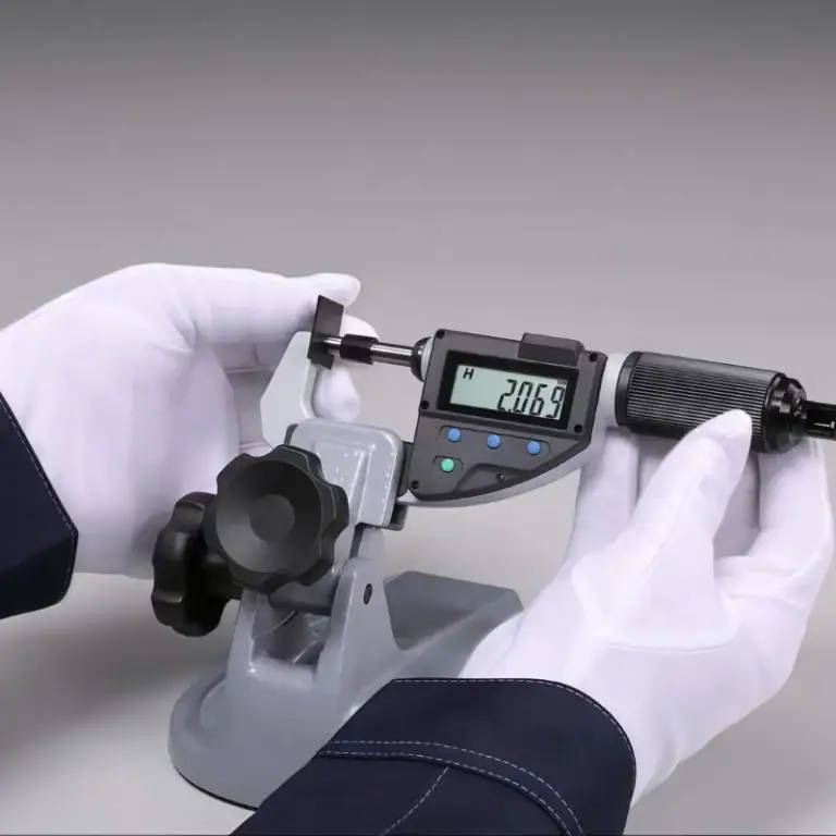
Inspection And Quality Verification
The final step involves dimensional inspection and quality validation. I measure critical tolerances—often up to ±0.01 mm under controlled machining conditions—and verify flatness, parallelism, and feature alignment. Surface finish and visual quality are also inspected. Only after confirming compliance with design specifications is the part approved for shipment.
Why Is Copper Difficult to Machine?
Copper may seem easy to cut due to its softness, but its high ductility and thermal conductivity create unique machining challenges. These properties affect chip formation, cutting stability, surface finish, and tool life, requiring optimized tooling and parameters.
Material Properties That Affect Copper Machinability
Copper machinability is influenced by several key mechanical and physical properties:
- Tensile strength– Determines cutting force requirements and machining stability.
- Hardness– Affects tool wear rate and resistance during cutting.
- Thermal conductivity– Influences heat distribution and dimensional control.
- Ductility– Increases the tendency for long chip formation and material deformation.
Alloy composition directly impacts how copper behaves under machining conditions.
Common Machining Challenges in Copper Processing
Copper machining presents several recurring technical challenges:
- Built-up edge formation– Material adhesion on the cutting edge reduces surface quality.
- Burr generation– Soft edges often require secondary finishing.
- Heat concentration– Localized heat may affect dimensional accuracy.
- Tool adhesion– Copper sticking to tools shortens tool life and reduces stability.
Effective tooling strategy and parameter optimization are essential for consistent results.
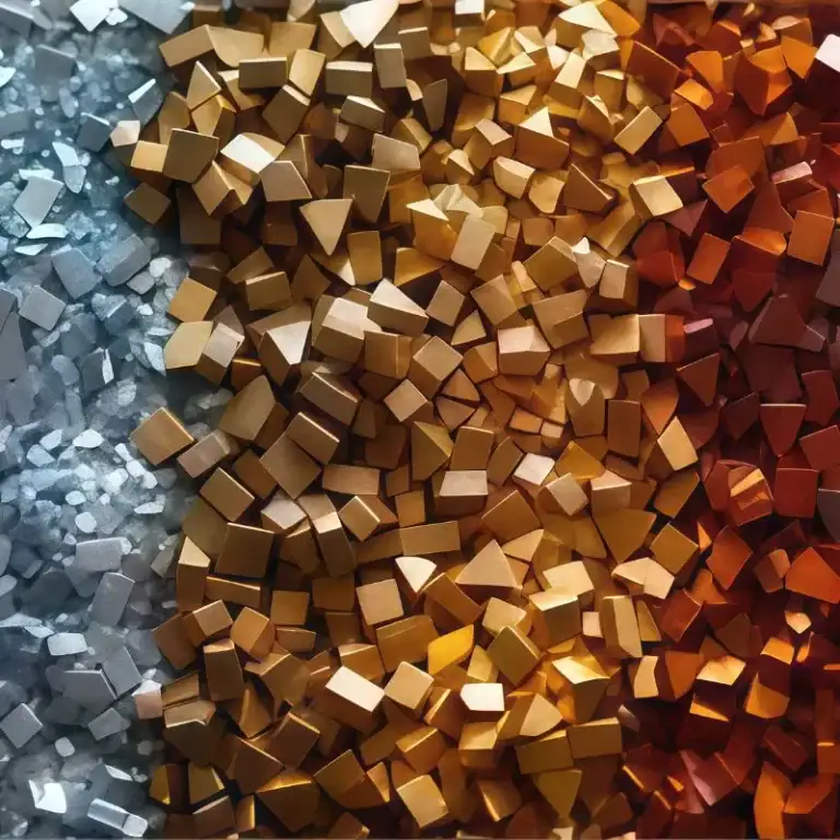
Which Copper Grades Are Suitable for CNC Machining?
Different copper grades vary in machinability, strength, conductivity, and cost. Choosing the right alloy requires balancing performance and production efficiency, as some alloys offer better chip control and tool life than pure copper.
| Copper Grade | Typical Standards | Machinability | Strength Level | Conductivity | Typical Applications |
| Pure Copper | C101, C102, C110 | Moderate | Low–Medium | Very High | Electrical connectors, busbars, heat sinks |
| Free-Machining Copper | C14500 | High | Medium | High | Precision turned parts, threaded components |
| Brass (Copper-Zinc) | C260, C360 | Very High | Medium–High | Moderate | Valves, fittings, structural components |
| Bronze | C932, C954 | Good | High | Moderate | Bearings, bushings, wear-resistant parts |
| Beryllium Copper | C17200 | Good | Very High | Medium | Aerospace components, high-strength springs |
Key Selection Insights
- Choose pure copperwhen conductivity is the top priority.
- Use free-machining copperwhen precision and tool life are critical.
- Select brass or bronzefor improved machinability and mechanical strength.
- Apply beryllium copperin high-load or wear-intensive environments.
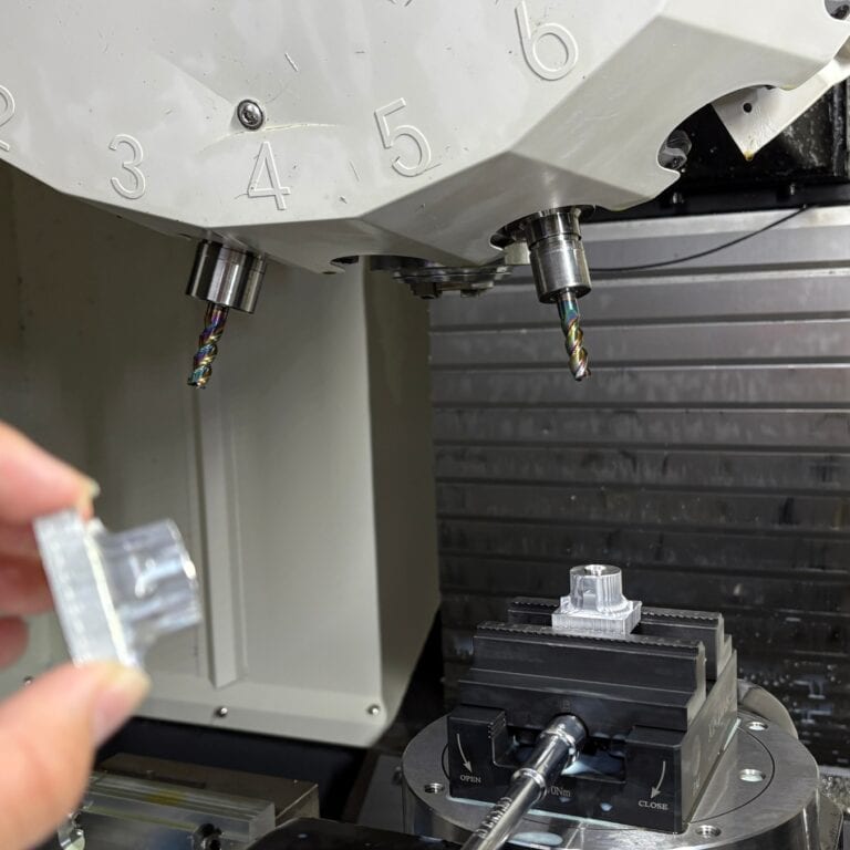
What Cutting Tools Are Best for Copper?
Tool selection is critical in copper machining. Because copper is soft and ductile, poor tool choice can cause smearing, built-up edge, and rapid wear. Proper tool material, coating, and geometry ensure stable cutting and longer tool life.
Carbide Tools for Copper Machining
Solid carbide tools are widely preferred due to their rigidity and wear resistance. They support higher cutting speeds and maintain sharp edges longer. For copper, polished carbide tools are especially effective in reducing material adhesion and improving chip evacuation.
High-Speed Steel (HSS) Tools
HSS tools are suitable for lower-speed operations and small-batch production. While more economical, they generally provide shorter tool life compared to carbide tools when machining copper.
Coated and Polished Tools
Standard hard coatings such as TiAlN may not perform ideally with pure copper because of adhesion risks. Polished surfaces or DLC-coated tools are often better options, as they reduce sticking and improve chip flow.
The Importance of Tool Geometry in Copper Machining
Tool geometry directly influences chip formation, cutting stability, and surface quality:
- High positive rake angle– Reduces cutting force and improves chip flow.
- Large clearance angle– Prevents rubbing and material adhesion.
- Polished flutes– Minimize chip sticking in soft copper alloys.
- Sharp cutting edges– Prevent smearing and improve surface finish.
Improper geometry may result in long continuous chips, unstable cutting conditions, poor surface finish, and dimensional inconsistency.
What Tolerances Can Copper CNC Machining Achieve?
Copper CNC machining can achieve high dimensional accuracy when proper tooling, machine rigidity, and cutting parameters are applied. However, tolerance capability depends on part geometry, copper grade, machining method, and production stability.
| Machining Method | Typical Tolerance | High-Precision Range | Surface Finish (Ra) | Notes |
| CNC Milling | ±0.02 mm | ±0.01 mm | 0.8–1.6 µm | Depends on tool sharpness and rigidity |
| CNC Turning | ±0.02 mm | ±0.01 mm | 0.8–1.2 µm | Good for concentric features |
| Precision Milling (Fine Pass) | ±0.01 mm | ±0.005 mm | 0.4–0.8 µm | Requires stable setup |
| Grinding (Secondary Process) | ±0.005 mm | ±0.002 mm | 0.2–0.4 µm | Used for critical surfaces |
What Design Considerations Should Be Followed?
Proper design improves machining stability, dimensional accuracy, and production efficiency. Because copper is soft and ductile, poor geometry can cause deformation, burrs, and unstable cutting. Designing for manufacturability reduces tool wear, cycle time, and overall cost.
Manufacturability
Design for manufacturability (DFM) is especially important when machining copper due to its material behavior under cutting forces.
To improve manufacturability:
- Avoid deep, narrow cavities that restrict chip evacuation and coolant flow
- Maintain sufficient wall thickness to prevent vibration and deflection
- Replace sharp internal corners with tool-friendly radii
- Minimize unnecessary ultra-tight tolerances on non-functional features
- Provide adequate flat surfaces for rigid clamping
- Design features aligned with machining direction to reduce repositioning
When copper parts are designed with tool access and rigidity in mind, cutting becomes more stable, surface finish improves, and dimensional accuracy is easier to maintain.
Cutting Parameters
Cutting parameter selection is critical in copper CNC machining because improper values can quickly degrade surface finish and tool life.
Key parameter considerations include:
- Use moderate-to-high spindle speeds to encourage clean shearing instead of material smearing
- Control feed rate to prevent long continuous chip formation
- Reduce radial engagement during finishing passes to improve accuracy
- Apply coolant or air blast to control localized heat buildup
- Adjust depth of cut depending on alloy hardness and machine rigidity
Balancing speed and feed is essential. Excessive speed can increase thermal distortion, while overly aggressive feed rates may cause burrs and dimensional deviation. Optimized parameter control ensures repeatability across production batches.
Where Is Copper CNC Machining Commonly Applied?
Copper CNC machining is widely used in industries that require high electrical conductivity, efficient heat dissipation, and reliable mechanical performance. Its ability to combine functional performance with tight tolerances makes it indispensable in modern precision manufacturing.
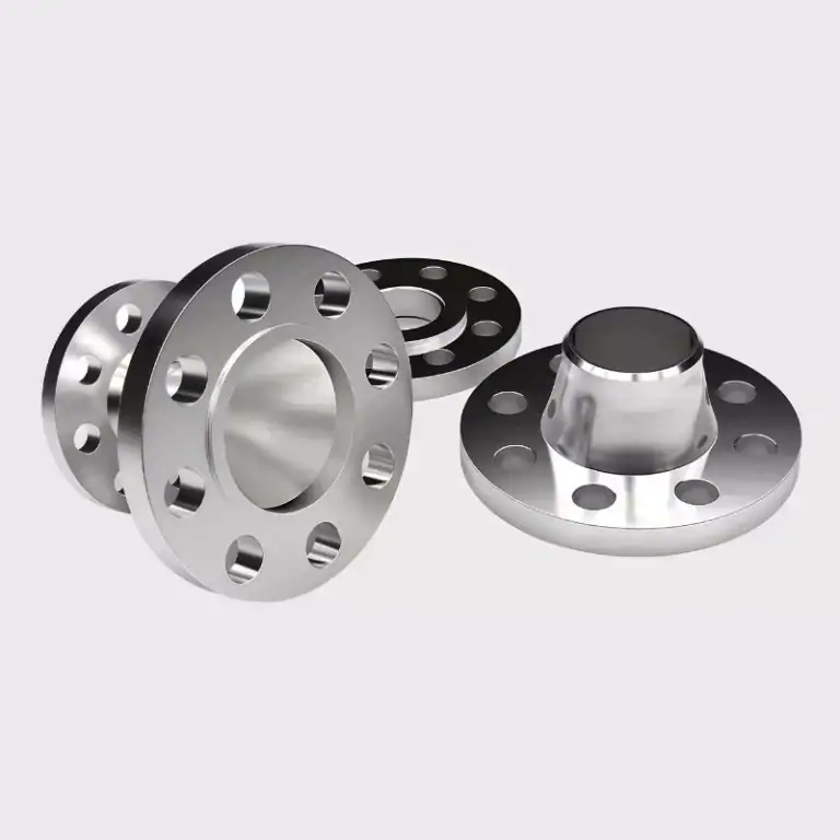
Electrical and Electronic Components
Copper is widely used in power distribution busbars, connectors, terminal blocks, and switchgear components due to its excellent electrical conductivity. In these applications, precise machining ensures stable contact pressure, reduced electrical resistance, and long-term performance reliability. Tight dimensional control is essential to prevent overheating and signal instability in high-current systems.
Thermal Management Systems
Copper’s superior thermal conductivity makes it ideal for heat sinks, cooling plates, liquid-cooled modules, and high-power semiconductor assemblies. Machining accuracy directly affects surface flatness and contact quality, which in turn influences heat transfer efficiency. Precision CNC machining ensures optimal thermal interface performance in demanding cooling applications.
Industrial and Automotive Applications
Copper CNC machining supports automotive electrical modules, hydraulic fittings, bearing components, and structural precision parts. In these sectors, components must maintain dimensional stability under vibration, load, and temperature variation. Reliable machining quality ensures durability and long service life in industrial environments.
Renewable Energy Systems
Copper components are critical in solar inverters, wind turbine assemblies, and energy storage systems where efficient power transmission is required. High conductivity and corrosion resistance enable stable energy flow and long-term operational reliability in renewable energy infrastructure.
Aerospace and Defense
In aerospace and defense applications, copper alloys such as beryllium copper are used for connectors, precision instruments, and high-strength contact components. These parts demand tight tolerances, structural integrity, and consistent performance under extreme operating conditions.
Telecommunications and Data Infrastructure
Copper CNC machining also plays an important role in RF connectors, communication terminals, and data center power distribution systems. Precision manufacturing ensures stable signal transmission, minimal electrical loss, and high reliability in communication networks.
What Factors Influence Copper CNC Machining Cost?
Copper CNC machining cost is determined by a combination of material characteristics, machining complexity, and production scale. Because copper is a relatively high-value material, waste reduction and process optimization significantly impact total project cost.
Primary cost drivers include:
- Copper alloy grade and market raw material pricing
- Part geometry complexity and feature density
- Required tolerance level and surface finish
- Machining cycle time and tool wear rate
- Setup, fixturing, and programming complexity
- Production volume and batch consistency
High-precision parts, thin-wall structures, and complex geometries typically increase machining time and tool consumption. Conversely, standardized design, stable batch production, and optimized cutting parameters reduce per-unit cost and improve overall manufacturing efficiency.
Understanding these cost variables helps engineers and procurement teams make informed decisions when planning copper CNC machining projects.
Why Choose CNC Machining for Copper Parts?
Copper components often require tight tolerances and reliable electrical or thermal performance. CNC machining delivers precise, repeatable results with efficient production control, making it ideal for high-performance copper parts.
Key advantages include:
High dimensional accuracy – Achieves tight tolerances for electrical and thermal components.
Consistent repeatability – Ensures stable quality across production batches.
Improved surface finish – Reduces secondary polishing and finishing work.
Efficient material utilization – Minimizes waste in high-value copper materials.
Capability for complex geometries – Supports multi-axis and intricate feature machining.
Scalable production – Suitable for prototyping, small batches, and medium-volume manufacturing.
Better cost control – Optimized machining strategies reduce cycle time and tooling wear.
FAQs
Can A CNC Cut Copper?
Yes, I can machine copper effectively using CNC systems with sharp carbide tools and optimized cutting parameters. Although copper is soft, its ductility requires proper chip control. With stable setups, I typically achieve tolerances around ±0.01 mm. Correct spindle speed and coolant use are essential to prevent smearing and tool adhesion.
Is Brass Or Copper Better For CNC Machining?
In my experience, brass is easier to machine than pure copper. Brass alloys like C360 have machinability ratings near 100 percent, while pure copper may range between 20–40 percent. However, copper offers much higher conductivity. I choose brass for efficiency and copper when electrical performance is the priority.
What Is CNC Copper?
CNC copper refers to copper components manufactured using computer-controlled machining processes. I use CNC milling and turning to produce precise copper parts for electrical and thermal applications. With optimized parameters, CNC copper machining ensures repeatable accuracy and consistent surface finish in batch production.
What Type Of Copper Is Used In Machining?
I commonly machine copper grades such as C101, C110, and C14500. Pure copper offers excellent conductivity, while C14500 improves machinability and tool life. For high-strength applications, I use beryllium copper like C17200. Material selection depends on balancing performance, strength, and machining efficiency.
Conclusion
Understanding copper CNC machining helps engineers balance alloy selection, tooling strategy, precision, and cost. The right machining solution depends on material grade, part geometry, and performance requirements.
At TiRapid, we support optimized copper CNC machining from prototype to production. Upload your design today and get a tailored machining solution.