CNC machining prototyping is a highly stable, precise, and reliable method for turning concepts into real products. Unlike 3D printing, it works with real materials, achieves tight tolerances, and supports fast iteration with smooth transition to mass production. This guide explains how modern teams can use CNC prototyping to speed up R&D, enhance design quality, and bring products to market more efficiently.
What Is Prototyping
In product development, a prototype is the first physical form of an idea—something you can touch, test, and evaluate. It is not the final product but a key validation tool that bridges concept and reality. Prototypes help identify issues early, reduce development costs, and ensure the design moves in the right direction.
Transitioning From Concept To Physical Form
To me, a prototype is the moment when a design becomes real.
It allows us to:
Transform a digital model into a physical part
Confirm that something “works on paper” also works in reality
Enable engineers and designers to make decisions based on a real, physical object
In other words, a prototype is one of the most important early decision-making tools in a product’s lifecycle.
The Role Of A Prototype In Product Development
Across many cross-industry projects, I’ve summarized three major values of prototyping:
Identify design issues early
A physical model quickly reveals problems such as:
Thin walls
Interference or clearance issues
Poor assembly fit
Insufficient strength
Accelerate team communication
With a real object in hand, teams no longer rely on imagination—alignment happens faster.
Reduce mass-production risks
Any issues resolved during the prototype stage save significant time and cost in later production phases.
Why Prototyping Is The Core Of Rapid Development
In today’s fast-paced product cycle, speed is a major competitive advantage.
The value of a prototype lies in its ability to support:
Rapid validation → Rapid modification → Rapid iteration
Continuous refinement with each build
Shorter DV (Design Verification), EV (Engineering Verification), and PV (Production Verification) timelines
That’s why I see prototyping as the gateway to fast and efficient product development—the starting point of a high-speed path toward final production.
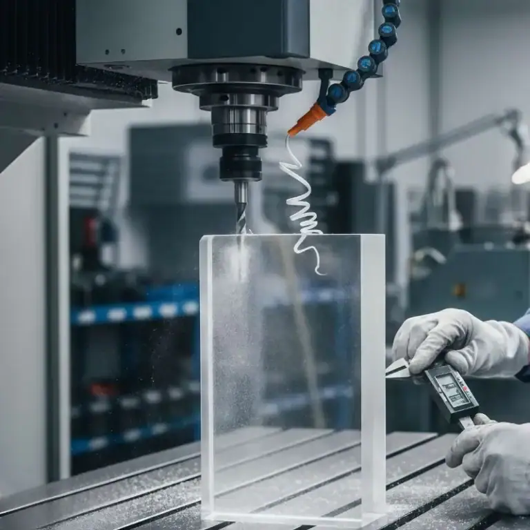
What Is CNC Machining Prototyping
CNC machining prototyping transforms 3D designs into precise, durable, and fully testable physical parts using subtractive manufacturing. It enables rapid iteration, accurate functional testing, and material-realistic verification—making it a preferred method in automotive, aerospace, medical devices, and consumer electronics.
How CNC Machining Works
CNC machining operates by removing material from a solid block through computer-controlled tools. The workflow involves:
CAD to CAM to G-code
Designs are converted into toolpaths that define cutting speed, depth, and motion.
In a robotics joint project, we used 5-axis machining with 0.005 mm tool compensation to meet a ±0.01 mm tolerance requirement.
Automated Cutting with Multi-Axis Control
CNC covers milling, turning, drilling, tapping, and fine surface machining.
Automation ensures exceptional dimensional consistency and is ideal for functional prototypes.
Real-Time Error Compensation
Advanced servo systems and probing allow the machine to automatically correct deviations—crucial for aerospace-grade prototypes.
The Role Of CNC Prototypes In Product Validation
Validating Structural Performance with Real Materials
Unlike 3D printing, CNC supports aluminum, steel, titanium, PEEK, nylon, and more—providing accurate, real-world mechanical behavior.
One medical client required drop-test verification: only CNC prototypes met the necessary strength.
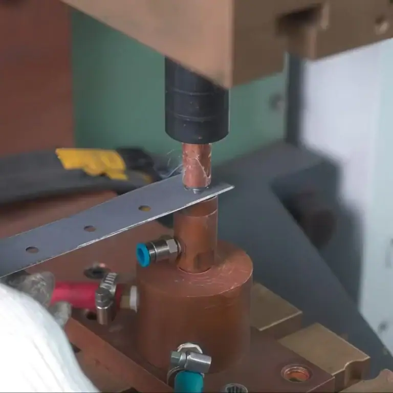
Assembly Fit & Interference Testing
CNC prototypes reveal real issues in holes, mating surfaces, threads, and tolerances.
In an EV cooling project, only the CNC prototype exposed a copper tube interference that CAD failed to predict.
Appearance & Ergonomics Verification
CNC allows smooth surfaces, sharp edges, tactile curves—critical for consumer electronics.
Risk Reduction & Faster Team Alignment
Any design issue fixed at the prototype stage prevents costly tooling errors later.
Key Characteristics Of CNC Prototyping
Precision
CNC offers:
±0.01 mm tolerances
Surface finish up to Ra 0.4–1.6 μm
Making it ideal for medical, aerospace, and robotics components.
Speed
No tooling required, production starts immediately:
Simple parts: 24 hours
Complex parts: 3–5 days
An automation customer received a complete aluminum prototype in 48 hours—one week ahead of their demo schedule.
Broad Material Compatibility
CNC supports the widest material range among all prototyping methods:
Metals: Aluminum, steel, stainless steel, titanium, brass
Plastics: ABS, PC, POM, PA, PEEK, Acrylic
Composites: FR4, carbon fiber
Ensuring functional prototypes match final production materials.
When Should You Choose CNC Machining For Prototype Development
CNC machining is the best choice when your prototype requires high precision, tight tolerances, real material performance, or fast iteration. It works with metals, plastics, and composites, supports functional testing, and transitions smoothly into small-batch production.

High Precision & Repeatability
CNC machining is ideal for engineering prototypes where accuracy cannot be compromised.
Tolerance capability as tight as ±0.01mm
Perfect for mechanical assemblies, mating parts, and functional components.
Consistency across multiple units
Servo-controlled toolpaths ensure every part matches the CAD model.
For example, in a robotics project I handled, 12 aluminum joint sets showed dimensional variation under 0.008mm—critical for smooth assembly.
Supports engineering validation (EVT)
CNC prototypes behave almost identically to production parts, making them suitable for stress, fit, and lifespan testing.
Wide Material Compatibility
CNC machining supports far more materials than common additive methods.
| Material Category | Specific Materials | Key Features & Typical Applications |
| Metals | Aluminum 6061 / 7075 | Lightweight, easy to machine, ideal for test fixtures, structural parts, and functional prototypes |
| Stainless Steel 304 / 316 | Corrosion-resistant, high strength, used in medical devices, outdoor parts, structural testing components | |
| Titanium Alloys | High strength-to-weight ratio, common in medical implants and aerospace experimental parts | |
| Engineering Plastics | ABS, PC | Cost-effective, impact-resistant, suitable for appearance models and light-duty structural components |
| POM, PA | Low friction, high wear resistance, ideal for sliding parts, gears, guide elements | |
| PEEK | Excellent high-temperature and chemical resistance, used for high-performance functional prototypes | |
| Composites | FR4 Fiberglass | Electrically insulating and dimensionally stable, used in electronic structural parts and fixture base plates |
| Carbon Fiber Plate | Ultra-lightweight, high stiffness, used in drones, robotics, and performance structural prototypes |
For example, I produced a clear PMMA flow-channel prototype that required optical transparency—something 3D printing could not achieve.
Faster Turnaround from Design to Part
When development speed matters, CNC machining delivers:
No tooling required
Simple parts: 24 hours
Complex parts: 3–5 days
Instant re-runs after design updates
Perfect for projects with continuous iteration.
Ideal for compressing DV→EV→PV cycles
In one EV battery project, we completed 8 prototype rounds in two weeks thanks to CNC machining’s rapid turnaround.
Smooth Transition To Low-Volume Production
Same process used for prototyping and pilot runs
Ensures smooth scaling and consistent part quality.
Cost-effective for 100–500 pcs
Much cheaper than building injection molds.
Suited for customized or frequently updated products
CNC machining remains the preferred solution for medical devices, drone components, industrial fixtures, and robotic parts.
What Processes Does CNC Machining Prototyping Involve
Turning a concept into a physical prototype requires a tightly coordinated CNC workflow. From CAD modeling and DFM review to toolpath programming, machine setup, machining, and inspection, every step influences accuracy, lead time, and cost. Understanding this full workflow helps teams iterate faster and transition smoothly into small-batch production.
Part Design & CAD Modeling
Every CNC action starts from the digital model.
Key considerations include:
Accurate geometry:For achieving tolerances down to ±0.01mm
Structural feasibility: Such as avoiding metal walls thinner than 0.8mm
Early assembly verification: To prevent costly rework
STEP and IGES files are generally ideal for CNC toolpath generation.
DFM Review & Process Route Planning
DFM determines whether the part can be manufactured efficiently and reliably.
Typical checks include:
Unmachinable geometries: Such as sharp inner corners requiring R0.5+
Number of setups: Especially important for 5-axis parts
Material suitability: Balancing stability, cost, and surface finish
A single DFM adjustment can often reduce machining time by 30–50%.
CAM Programming & Toolpath Strategy
CAM defines how the machine cuts material—similar to a navigation map.
Key factors include:
Toolpath strategies (roughing, finishing, adaptive milling)
Feed rates, spindle speeds, and stepovers
Techniques to reduce chatter, burrs, and surface marks
For clear PC prototypes, I often use high-speed finishing with light stepovers to minimize polishing time.
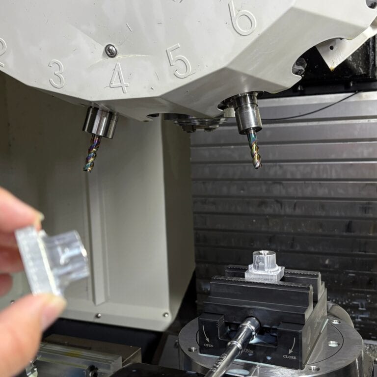
Machine Setup, Tooling & Fixturing
Proper setup greatly affects machining precision.
Critical tasks include:
Selecting the right cutters (O-flute for aluminum, multi-flute for steel)
Using proper fixturing (vacuum tables for thin sheets, clamps for blocks)
Machine calibration and thermal compensation
In aerospace projects, improper thermal compensation can cause deviations up to 0.05mm on long parts.
Machining, Inspection & Iteration
Post-machining evaluation ensures prototype accuracy:
Dimensional measurement (calipers, CMM)
Surface and defect inspection
Assembly fit testing
I recommend keeping two prototype versions:
Version A: Design/structure validation
Version B: Production-like version
This improves decision-making for both engineers and sourcing teams.
How To Transition From Prototype To Small-Batch Production
Key strategies for smooth scaling include:
Standardizing datums and fixturing
Relaxing tolerances where possible
Creating repeatable process documentation
I often prepare a “Production Readiness Package” for clients to ensure consistent quality across 100–1000+ units.
What DFM Principles Should You Follow When Designing CNC Prototypes
DFM is essential in CNC prototyping because it determines machinability, cost, accuracy, and lead time. Understanding how wall thickness, fillets, hole sizes, tolerances, and setup requirements affect machining can significantly improve prototype quality and reduce iteration cycles.
Wall Thickness, Fillets, Hole Sizes, And Fine Features
Wall Thickness Guidelines
Minimum recommended thickness: metal ≥0.8mm, plastics ≥1.2mm.
Thin walls cause vibration, deformation, and breakage, especially in 7075 aluminum and brittle plastics.
Example:
A medical housing with a 0.5mm wall repeatedly deformed during machining. Increasing it to 1mm solved the issue.
Fillets That Match Tool Diameter
Inside corners must have fillets, CNC tools cannot cut sharp internal corners.
Smallest common tool diameter: Ø1mm (R0.5). Deep cavities require even larger fillets.
Rule of thumb:
Deeper cavity → larger fillet → higher machining stability.
Hole & Feature Constraints
Minimum hole diameter: ≥1mm unless micro drilling is acceptable.
Hole depth should not exceed 6× its diameter to maintain straightness and surface quality.
Pro tip:
Convert blind holes to through holes when possible to improve chip evacuation and reduce cost.
Tolerances, Fits, And Surface Roughness
Set Realistic Tolerances
Non-critical dimensions: ±0.1mm.
Critical fits: H7/g6, ±0.01mm, or based on functional requirements.
Common mistake:
Applying ±0.01mm to the entire drawing, which increases cost by 2–5× without necessity.
Suggested Surface Roughness Levels
Standard appearance parts: Ra1.6–3.2
Optical PMMA parts: require polishing for clarity
Precision sliding components: Ra0.8 or better
We have produced optical-grade PMMA lenses using high-speed machining combined with hand polishing, achieving full transparency.
How To Design To Reduce Setups And Machining Time
Reducing setups improves accuracy and reduces cost.
Make Features Accessible From Fewer Directions
Avoid distributing critical features across too many faces.
Add Non-visual Reference Surfaces
Extra datums or clamping areas improve machining stability.
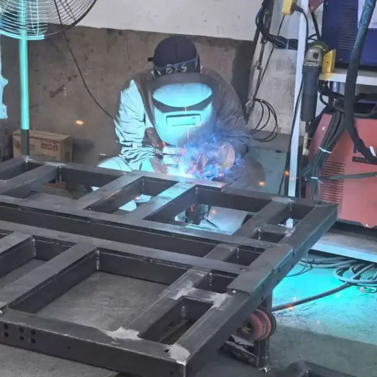
Split Complex Designs Into Assemblies
For example, a deep robotic housing was redesigned into two pieces, reducing cost by 40% and cutting lead time in half.
How To Prepare High-Quality CAD Models And Drawings
Good CAD Models
Watertight solids, no missing surfaces
Properly exported STEP files
Clear reference geometry and datums
Good Engineering Drawings
Only necessary tolerances
Surface finishes, chamfers, fillet details
Default tolerance standards (ISO2768, etc.)
Over 70% of machining errors we see come from incomplete or unclear drawings.
Common Design Mistakes And How To Avoid Them
Expecting Sharp Internal Corners
CNC tools cannot cut a perfect 90° inner corner → add fillets.
Uneven Wall Thickness
Causes warping, especially in plastics → maintain uniformity.
Unmachinable Features
Deep narrow slots, enclosed cavities → check for tool accessibility.
Overly Tight Tolerances
Drives cost up unnecessarily → reserve tight tolerances for functional areas only.
Missing Datums
Leads to clamping errors → always provide at least one clear reference plane.
What Machining Processes And Equipment Are Common In CNC Prototyping
Choosing the right CNC process and equipment directly determines prototype accuracy, speed, functionality, and scalability. From 3-axis milling to advanced 5-axis machining, from turning to grinding, each method has unique advantages. Understanding these capabilities helps engineers optimize manufacturability, reduce risk, and move prototypes smoothly into small-batch production.
CNC Milling (3-Axis, 4-Axis, 5-Axis)
Milling is the most widely used process in CNC prototyping. I typically select the milling configuration based on the part’s geometric complexity:
3-Axis Milling
Ideal for most flats, pockets, slots, steps, and basic contours
Best for simple structural components
Examples: electronic housings, brackets, machined base plates
4-Axis Milling
Adds one rotational axis, enabling multi-face machining and reducing setups
Improves accuracy for features around cylindrical parts
Examples: side grooves on cylinders, gear profiles, helical grooves
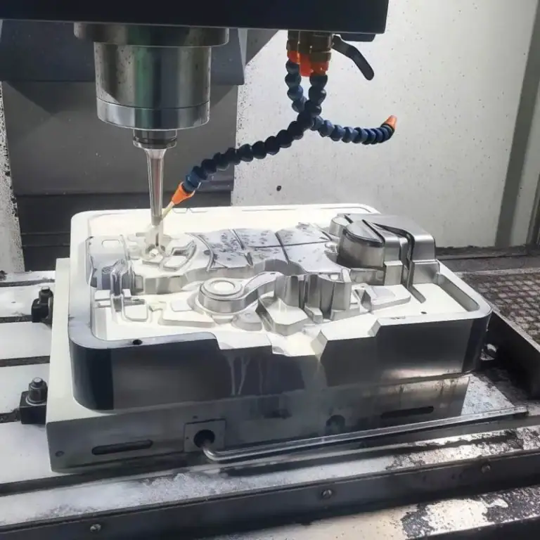
5-Axis Milling
Handles complex curved surfaces, deep cavities, and highly detailed geometries
Ensures superior precision and fewer fixturing operations
Examples: turbine blades, optical curved surfaces, complex housings
When making aerospace prototypes, I rely heavily on 5-axis machining because it significantly reduces setup time and delivers much higher accuracy.
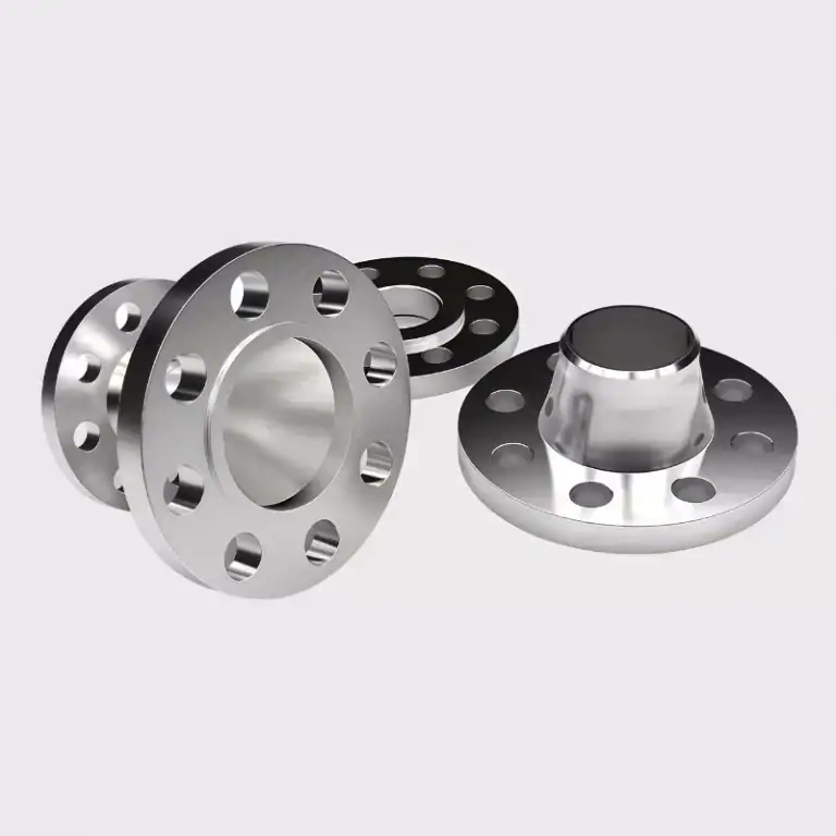
CNC Turning & Turn-Mill Machining
Turning is ideal for any part with rotational features, such as shafts, bushings, screws, and connectors.
Advantages of Turning
Roundness tolerance can reach ±0.005 mm
Extremely fast material removal, making it one of the most cost-efficient processes
Turn-Mill (Mill-Turn) Machining
Turn-mill machines integrate turning and milling on the same equipment, enabling:
Complex end-face features
Off-center holes
Keyways, grooves, and multi-surface details
I frequently use turn-mill machining for robot joints, hydraulic connectors, and automation shafts, as it dramatically reduces setup changes and eliminates accumulated errors.
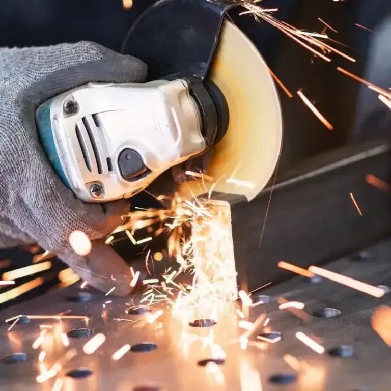
Grinding & High-Precision Surface Finishing
When a surface requirement reaches Ra 0.4 or even a near-mirror finish, grinding is often the only process that can meet the specification.
Surface grinding: ideal for plates, frames, and mold bases
OD grinding: for high-precision shaft geometries
ID grinding: used for H6-grade or tighter tolerance holes
One memorable case was a medical equipment slide rail that required ±0.005 mm flatness—a level of precision we achieved only after fine surface grinding.
Common CNC Equipment Used In Prototype Manufacturing
Typical machines include:
3-axis / 4-axis / 5-axis CNC mills: cover 90% of prototype part geometries
CNC lathes & turn-mill centers: highly efficient for rotational components
High-speed machining centers: ideal for transparent parts and micro-features
Surface, OD, and ID grinders: required for ultra-high surface accuracy
Small-hole EDM: handles deep, narrow slots and sharp internal corners
When selecting equipment, I generally evaluate:
Geometric complexity
Tolerance and surface requirements
Cost and lead time targets
What Are The Key Advantages And Limitations Of CNC Machining Prototyping
CNC prototyping is widely used because it balances precision, strength, material availability, and iteration speed better than most other methods. However, it also comes with natural limitations such as material waste, geometric constraints, and higher costs for single units. This section breaks down both sides so teams can choose the right method confidently.

Key Advantages Of CNC Prototyping
High Precision and Tight Tolerances
CNC machining consistently achieves ±0.01 mm and can reach ±0.005 mm with optimized setups.
In one medical-device project, we achieved a flatness of 0.008 mm—critical for ensuring smooth motion and consistent performance.
This level of accuracy reduces design risks early in development.
Structural Stability and Functional Testing
CNC prototypes use real engineering materials such as aluminum, stainless steel, POM, and PEEK.
This allows:
Full load testing
Durability and fatigue evaluation
Environmental/thermal testing
Precise assembly verification
For example, our 7075 aluminum prototype for a robotic reducer passed a 200-hour dynamic fatigue test.
High Repeatability for Small Batches
Digital programming ensures that each unit remains consistent, making it ideal for 5–200 functional prototypes.
In an EV control system project, all 30 prototypes stayed within ±0.02 mm, ensuring stable testing results.
Fast Lead Times for Rapid Iteration
No tooling is required, enabling delivery in 24 hours to 5 days.
This supports:
Faster design cycles
Rapid validation
Shorter overall development timelines
One optical fixture project completed four iterations in a single week.
Ability to Produce Complex Geometries (Within Subtractive Limits)
5-axis machining enables:
Deep cavities
Multi-angle drilling
Complex curves
Aerodynamic structures
Aerospace turbine blades are a typical example where 5-axis machining significantly improves accuracy and reduces setups.
Cost Advantages in Specific Scenarios
CNC machining becomes cost-effective when:
Functional strength is required
Tolerances are strict
Small batches are needed
Material must match final production
A customer avoided a $20,000+ mold by choosing CNC machining, producing 10 functional parts for under $2,000.
Limitations And Challenges Of CNC Prototyping
Material Waste From Subtractive Manufacturing
CNC machining typically uses only 30%-60% of the raw material.
For high-cost materials like titanium and PEEK, this significantly impacts cost, even when chips are recycled.
Geometric Constraints Compared to 3D Printing
CNC tools must physically reach the cutting area, limiting:
Enclosed cavities
Deep, narrow internal channels
Highly complex hollow structures
A fluid-channel component from a client could only be produced using additive manufacturing.
Dependence on Programming, Fixturing, and Operator Skill
Quality relies on:
CAM programming
Tool selection
Fixturing design
Operator experience
We once received a “failed prototype” from another supplier due to poor toolpath planning that ruined the entire block of aluminum.
Higher Cost Per Part, Not Economical for Large Volumes
Ideal for 1–200 pieces, but once quantities reach thousands, molding or casting becomes more economical.
Environmental & Sustainability Concerns
Main impacts include:
Metal and plastic chip waste
Coolant consumption
High energy usage
Recycling metal chips and choosing eco-friendly coolant can help reduce environmental impact.
What Factors Should Be Considered In CNC Prototype Production Lines
Building an efficient CNC prototyping pipeline requires more than machining capabilities. Material choice, part complexity, accuracy requirements, batch quantities, and supplier capabilities all play major roles in determining cost, lead time, and overall project success.
Cost Components
CNC machining costs come from four primary elements.
Material Cost
Material prices can vary dramatically:
Aluminum 6061: baseline cost
7075: 30%-50% higher
Stainless steel: 2–3× the cost of aluminum
PEEK: extremely high-end engineering plastic
A recent aerospace bracket project reduced total cost by 40% simply by switching from 7075 to 6061.
Machining Time
Driven by programming time, toolpath complexity, and number of setups.
5-axis parts often require 3–5× longer machining time
Deep cavities often need multiple roughing and finishing passes
Structural Complexity
Factors include:
Deep pockets, thin walls, sharp internal corners
Multiple-face machining
Tight tolerances and precision fits
More complexity = higher risk = higher cost.
Batch Quantity
Larger batches significantly reduce per-unit cost.
Producing 10 units instead of 1 often halves the unit cost due to shared programming and setup time.
Balancing Accuracy, Speed, And Budget
Accuracy-First
Used for functional testing and assembly verification.
±0.01mm tolerance
Longer machining time
Higher cost
Common in: medical instruments, precision rails, automation components.
Speed-First
Used for early-stage design and appearance verification.
±0.1mm tolerance
Simplified toolpaths
Ideal for concept models and display units
I often recommend this approach during early development to save time and budget.
Budget-First
Suitable for non-critical or auxiliary parts.
Simplified geometry
Cheaper materials
Relaxed tolerances
Typical use: fixtures, testing jigs.
When To Transition From CNC Prototyping To Molding Or Mass Production
Quantity Thresholds
1–200 pcs: CNC is ideal
200–1000 pcs: CNC + fixtures
1000+ pcs: consider molding, die casting, or injection molding
Cost-Reduction Requirements
When the target cost per unit must drop significantly, molding becomes the only viable option.
Late-Stage Validation (EV/PV)
Once the design stabilizes, tooling can begin.
Geometry Not Suitable for CNC Mass Production
E.g., thin shells, complex internal flow channels.
How To Select And Manage External Suppliers
Key Supplier Selection Criteria
Machine capability (5-axis, turning-milling, high-speed machining)
Quality certification (ISO9001)
Inspection capability (CMM, roughness testers)
Lead-time performance (24-hour prototyping capability)
Best Practices for Supplier Management
Provide complete drawings and DFM notes
Ask for milestone progress updates
Verify inspection data against drawings
The most effective communication workflow I use is:
“Drawings + 3D model + key tolerance list + appearance requirements + inspection method.”
This reduces misunderstanding and dramatically lowers rework rates.
How To Ensure The Best Results In CNC Machining Prototyping Projects
In the prototyping stage, speed, accuracy, and communication quality often determine the final outcome more than the machining itself. A successful CNC prototyping project hinges on selecting a suitable machining facility, clearly defining tolerances and functional requirements, establishing an efficient iterative mechanism, and using scientific testing methods to ensure the samples meet expectations.
How To Choose The Right CNC Machine Manufacturer
Selecting the right supplier is crucial for achieving precision, speed, and reliability.
Match equipment capability to your part
Simple housings → 3-axis
Deep cavities, complex surfaces → 5-axis
Shafts, connectors → turning or turn-milling
Example: A robotic joint with angled holes required 4-axis machining, otherwise cost increased threefold.
Evaluate quality and inspection capability
Look for:
ISO9001 certification
CMM, vision inspection, roughness testing
Material traceability
A shop without adequate inspection will inevitably cause delays and rework.
Engineering communication quality
A good supplier should provide DFM feedback and fully understand functional requirements.
Lead time consistency
Strong vendors can support:
24-hour prototyping
Fast small-batch turnaround
Emergency rework
How To Communicate Tolerances, Appearance, And Functional Requirements Clearly
Most prototype failures come from unclear requirements—not machining mistakes.
Define tolerances explicitly
Identify:
Critical tolerances (e.g., ±0.01mm)
Non-critical regions
Fit and alignment requirements
Lack of tolerance information once caused an entire fixture assembly to fail during one of my projects.
Specify appearance expectations
Include notes on:
Surface tool marks allowed or not
Anodizing/plating color requirements
Scratch acceptance level
Directional grain patterns
Clarify functional intent
Machinists must understand:
Required smoothness or clearance
Sealing surfaces
Impact or temperature requirements
Function-oriented communication helps the supplier choose optimal processes.
How To Iterate Designs Efficiently
Prototyping is about learning fast—not perfection on the first attempt.
Use quick-turn prototypes for early validation
Relax tolerances and use economical materials to accelerate feedback.
Improve designs one iteration at a time
Focus each round on the highest-priority issues:
Interference
Strength
Fit tolerance
This reduces cost and accelerates progress.
Maintain synchronized communication
Use an Issue List to document each revision’s goals and findings.
This helps suppliers stay aligned with the engineering intent.
Inspection Methods & Quality Control in the Prototype Stage
Even prototypes require structured inspection to ensure meaningful validation.
Appearance inspection
Tools:
Inspection lamps
Gloss meters
Color meters
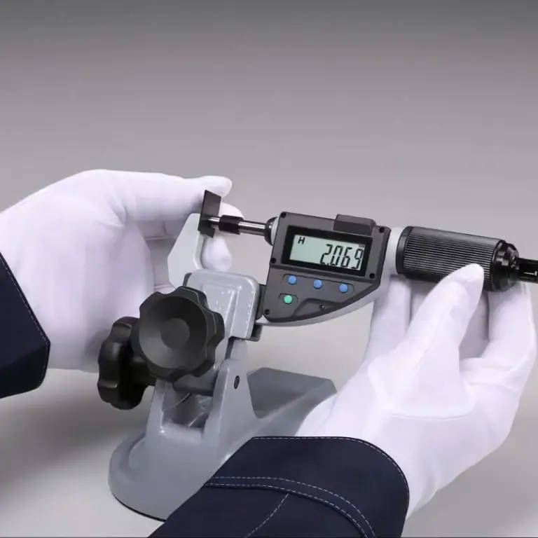
Dimensional inspection
Choose based on tolerance requirements:
Calipers: ±0.02mm
Micrometers: ±0.005mm
CMM: ±0.002mm
In medical projects, we required every critical hole to pass CMM verification.
Functional testing
May include:
Assembly fit
Torque testing
Friction/sliding resistance
Leak or pressure testing
These tests directly guide the next design iteration.
Industries That Commonly Use CNC Prototyping
CNC prototyping is widely used across automotive, aerospace, medical, consumer electronics, and industrial automation industries. These sectors rely on high precision, material versatility, structural validation, and rapid iteration to accelerate product development.
| Industry | Typical Prototyping Needs | Common Materials | Example Prototype Parts |
| Automotive & New Energy | Strength testing, structural components, thermal management, precision fit validation | Aluminum 6061/7075, Stainless Steel 304/316, POM, PA, PC | Battery trays, motor housings, gearbox components, test fixtures, heat-dissipation modules |
| Aerospace & Defense | Lightweight structures, complex surfaces, high-strength functional prototypes | Aluminum 7075, Titanium alloys, Magnesium alloys, High-performance plastics | Turbine blades, structural frames, connectors, radar housings, linear guides |
| Medical & Life Sciences | High precision, corrosion resistance, biocompatibility testing | Stainless Steel 316L, Titanium alloys, PEEK, Clear PC/PMMA | Surgical tools, implant test parts, medical jigs, sliding rails, instrument housings |
| Consumer Electronics & Smart Devices | Appearance models, structural fit testing, heat dissipation validation | Aluminum alloys, Stainless steel, ABS, PC, Magnesium alloys | Smartphone frames, laptop housings, camera brackets, structural skeletons |
| Industrial Equipment & Automation | Wear-resistant parts, fixturing, motion mechanism validation | Steel, Aluminum, POM, PA, Carbon fiber sheets | Shafts, guide blocks, automation fixtures, connectors, robotic arm components |
| Architecture, Structural & Cross-Industry Applications | Large structural mockups, assembly validation, functional testing | Aluminum profiles, Stainless steel, FR4, Composite panels | Structural nodes, mounting hardware, connector blocks, lighting brackets |
FAQs
What Factors Determine Prototype Costs?
Prototype cost is mainly driven by part complexity, machining time, material choice, and tolerance requirements. From my experience, tight tolerances can increase costs by 20–40%, while complex 5-axis geometries may double cycle time. Quantity also matters—single-piece runs carry higher setup costs. Surface finishing, inspection needs, and design revisions further influence overall pricing.
What Is The Typical Delivery Cycle For A CNC Prototype?
Most CNC prototypes ship within 3–7 days in my projects, depending on complexity and material availability. Simple aluminum parts may be completed in 24–48 hours, while multi-setup components requiring 5-axis machining or CMM inspection can extend lead time to 7–10 days. Express schedules are possible when programming and fixturing are straightforward.
When Should CNC Machining Be Prioritized?
I prioritize CNC machining when the prototype demands high precision (±0.02 mm or tighter), real material properties, or functional testing. CNC is also ideal when surface quality, durability, and structural evaluation are essential. If the design will later enter low-volume production, CNC ensures the prototype matches production intent with minimal process deviation.
How Consistent Are Prototypes With Production Parts?
CNC-machined prototypes are typically 90–100% consistent with production parts when using the same material and tolerance specs. In my workflow, using identical toolpaths and fixturing can replicate geometry within microns. This consistency allows accurate fit-testing, functional validation, and mechanical benchmarking before committing to tooling or larger production runs.
When Should You Switch From CNC Machining To Injection Molding Or Other Processes?
I recommend switching to injection molding when production exceeds 100–500 units, depending on part size and complexity. CNC is ideal for early validation, but molding becomes more cost-effective for repeat volumes. If the design stabilizes, surface texture requirements increase, or cycle cost must drop significantly, transitioning to molds is the optimal path.
Conclusion
In my prototyping work, CNC machining has always been the fastest and most reliable way to turn a concept into a testable part. It delivers near-production quality, enabling rapid verification of design, strength, and assembly within days. To truly shorten development time and reduce rework, you need more than machining—you need the right design approach, materials, and process strategy. For any CNC prototyping needs, contact us for you best solution!