CNC aerospace machining is the backbone of modern aerospace systems, where precision, safety, and compliance are paramount. In this article, I will introduce you to the definition of aerospace CNC machining, the components that rely on it, how material and process choices affect machining outcomes, and the strategies that ensure micron-level accuracy. This will help you understand how precision machining is achieved in one of the most demanding industries on Earth.
What Is CNC Aerospace Machining
Precision machining in aerospace is not just about cutting metals—it’s about meeting standards where tolerances are often within ±2–10 μm and surface finishes must achieve Ra 0.2 μm or better. In this section, I’ll explain the fundamentals, why accuracy is mission-critical, and what benchmarks define aerospace-grade machining.
What Is Aerospace CNC Machining
CNC aerospace machining refers to subtractive manufacturing processes—milling, turning, EDM, grinding—used to create mission-critical aircraft and spacecraft parts. Unlike consumer industries, every component here must pass AS9100D or FAA/EASA requirements. I’ve worked with parts like hydraulic manifolds and turbine blades, where even a 5 μm error can ground an aircraft.
Why Is Precision Critical In Aerospace CNC Machining
Safety & Certification
In aerospace, even a ±10 μm deviation in landing gear brackets can reduce load capacity and risk failure. FAA data shows 25%+ of incidents stem from structural issues. To prevent this, parts are checked with CMM (±2 μm repeatability) and NDT methods, ensuring turbine blades, spars, and landing gear remain reliable under extreme stress.
Traceability
Traceability links each part to its material lot via AS9102 FAI digital records. In 2023, Airbus managed 95% of CNC parts with digital traceability, cutting recall risks by 40%. Advanced systems like RFID and blockchain ensure visibility and accountability across the aerospace supply chain.
Regulatory Compliance
Meeting AS9100D, ITAR, NADCAP is mandatory. Certified suppliers often achieve 98% FPY, versus 85–90% for non-certified. NADCAP audits cover special processes like heat treatment and coatings. Non-compliance can mean supply chain removal, multimillion penalties, or even aircraft grounding.
Typical Tolerances And Surface Standards In Aerospace CNC Machining
Linear Tolerances
Aerospace components require ±0.002 mm–0.01 mm linear tolerances.
This precision is about 5–10 times stricter than the ±0.02–0.05 mm range common in automotive parts.
For example, even a few microns of deviation in wing spars or landing gear brackets can affect load distribution and flight safety.
Surface Roughness
Critical aerodynamic parts such as turbine blades demand Ra ≤ 0.2 μm.
This level ensures reduced turbulence and friction losses when blades rotate at speeds exceeding 20,000 RPM.
By contrast, consumer electronics often require only Ra ≈ 1.6 μm to meet visual and functional needs.
Circularity / Roundness
Bearing housings must achieve roundness within ≤0.005 mm.
This ensures stability at extreme operating speeds of 20,000–30,000 RPM, preventing vibration and premature wear.
As a comparison, most general mechanical industries accept roundness levels of 0.02–0.05 mm.
Aerospace tolerances are often stricter by an order of magnitude compared with automotive and electronics sectors.A tolerance of ±0.002 mm, routine in aerospace, is almost unheard of in consumer electronics.These demanding standards guarantee compliance with AS9100, FAA, and EASA certifications, ensuring parts remain reliable under extreme conditions.
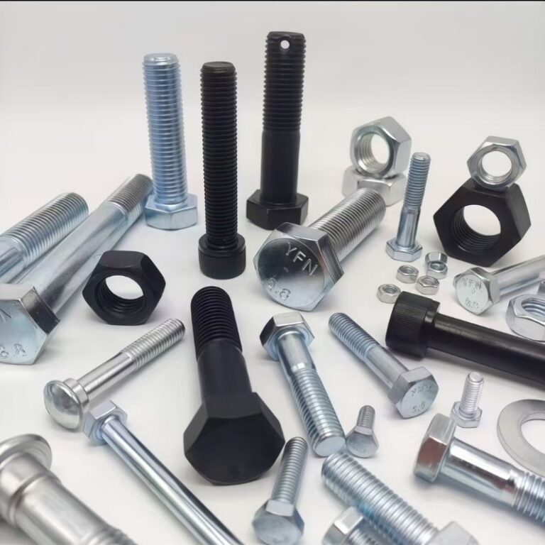
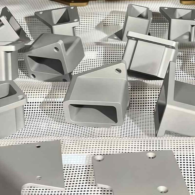
Which Aerospace Components Use CNC Machining
CNC machining plays a pivotal role across aerospace subsystems, from structural elements to MRO. Structural parts like ribs, spars, and bulkheads require ±5 μm precision, while engine components such as turbine blades and landing gear joints demand high-strength alloys. Avionics housings must fit within 0.1 mm to avoid EMI, and cabin tracks or hatches withstand >20,000 psi. CNC also supports space systems and extends component life 20–30% through re-machining in MRO.
Structural Components
Ribs
Aircraft ribs define the aerodynamic shape of wings and distribute loads across the airframe.
Most ribs are CNC-milled from aluminum 7075 due to its excellent strength-to-weight ratio (~570 MPa tensile strength).
Even though modern aircraft like the Boeing 787 is ~50% composite by weight, aluminum ribs remain critical because composites often require metallic reinforcement.
CNC machining ensures linear tolerances within ±5 μm, preventing distortion under aerodynamic loads exceeding 3–5 g during maneuvers.
Spars
Spars act as the primary load-bearing structures in wings and tail sections.
These are frequently machined from CFRP laminates or high-strength aluminum alloys, balancing stiffness with weight reduction.
A typical wing spar in large aircraft can reach 15–20 m length, requiring 5-axis CNC milling centers with advanced vibration control.
Precision machining avoids stress concentrations that could reduce fatigue life, which in aerospace typically targets >60,000 flight cycles.
Bulkheads
Bulkheads provide structural integrity for the fuselage, distributing pressurization forces and impact loads.
High-strength alloys such as 7075-T6 aluminum or titanium are CNC-machined to meet both weight reduction and crashworthiness requirements.
A single bulkhead may withstand cabin pressurization loads equivalent to 8–9 psi differential pressure, requiring dimensional consistency better than ±0.01 mm across large curved surfaces.
Multi-axis CNC machining enables integration of complex cutouts for wiring, hydraulic lines, and mounting interfaces, improving assembly efficiency.
Engines And Powertrain
Turbine Blades
Turbine blades are typically machined from Inconel 718, a nickel-based superalloy that retains strength at temperatures above 700–800°C.
Precision is critical: dimensional tolerances often need to be controlled within ±0.02 mm, ensuring aerodynamic efficiency and preventing fatigue failure during continuous operation at 20,000–30,000 RPM.
Even a slight deviation in blade geometry can increase fuel consumption by 1–2% per flight, resulting in millions of dollars in additional operating costs across an airline fleet.
Gearbox Housings and Engine Mounts
CNC machining ensures that gearbox housings meet strict alignment requirements, keeping gear meshing error below 10–15 μm, which is vital for vibration control and transmission efficiency.
Engine mounts must withstand both static and dynamic loads from thrust and vibration. For example, in widebody aircraft, mounts often support loads exceeding 100–150 kN.
Multi-axis machining and real-time probing systems are applied to maintain consistent accuracy across these large, complex castings.
Landing Gear Beams and Joints
Landing gear beams and joints are usually manufactured from 300M steel (a modified 4340 alloy), chosen for its ultimate tensile strength of ~1930 MPa and high fracture toughness.
CNC machining operations include deep-hole drilling (depth-to-diameter ratio > 20:1), stress-relief heat treatments, and precision finishing.
Each gear beam may endure >100,000 takeoff/landing cycles, so tight tolerances and residual stress control are mandatory to prevent fatigue cracks.
Avionics And Electrical Housings
Dimensional Accuracy
Avionics connectors and housings demand micron-level precision. Even a 0.1 mm misalignment can cause electromagnetic interference (EMI) or poor contact integrity, which directly threatens aircraft safety.
CNC machining enables tolerances within ±0.01–0.05 mm, ensuring seamless assembly with complex wiring harnesses and shielding systems.
Material Requirements
Common materials include aluminum 6061/7075, stainless steels, and high-performance polymers (PEEK, Ultem).
Aluminum housings combine lightweight with high electrical shielding, stainless steel provides durability in high-vibration zones, polymers offer insulation and weight reduction.
For example, PEEK housings are rated to withstand continuous service temperatures up to 250°C while maintaining dielectric strength.
Surface Finish and Coatings
Precision housings often require surface roughness Ra ≤ 0.8 μm to ensure tight sealing against dust, moisture, and EMI leakage.
Post-processing includes anodizing, chromate conversion, or nickel plating, which can improve conductivity and corrosion resistance by 20–30%.
Functional Performance
Avionics systems rely on thousands of connectors and housings per aircraft. For instance, a modern commercial jet may contain 100–150 km of wiring with thousands of connection points.
CNC machining ensures that each housing not only meets fit and tolerance requirements but also supports long-term reliability under 10,000+ flight cycles.
Compliance and Testing
All avionics housings must meet RTCA/DO-160 environmental standards and AS9100 certification for aerospace quality.
Testing involves vibration, thermal cycling (−55°C to +125°C), and salt fog resistance, ensuring connectors operate flawlessly throughout service life.
Interior/Exterior And Doors
CNC machining plays a vital role in producing both interior and exterior aerospace components, where strength, precision, and safety are non-negotiable.
Seat Tracks & Cabin Structures
Seat tracks, which anchor passenger seating, are CNC-milled from 7075 aluminum alloys, known for their strength-to-weight ratio. A typical seat track must withstand loads exceeding 16g during emergency landings, requiring tolerances within ±0.01 mm.
Access Panels & Hatches
Maintenance hatches and inspection panels are CNC-machined to achieve perfect sealing and alignment. Even a 0.05 mm misalignment can compromise pressurization or allow moisture ingress, risking long-term corrosion.
Doors Under Extreme Pressure
Aircraft doors endure some of the highest stresses. At cruising altitude, cabin pressure differences exceed 20,000 psi (≈137,000 kPa). CNC machining ensures perfect geometry and fit of hinges, locking mechanisms, and sealing interfaces. Any deviation beyond ±0.005 mm could lead to catastrophic safety risks.
Exterior Trim & Fairings
Exterior fairings, winglets, and decorative trims are CNC-milled to optimize aerodynamics while reducing drag. Surface finishes are kept below Ra 0.4 μm, ensuring smooth airflow and minimal turbulence.
Through these processes, CNC machining guarantees that interior and exterior aerospace components not only meet FAA/EASA safety requirements but also extend durability under repeated pressure cycles and extreme operating conditions.
Aerospace, Space, And MRO
CNC machining is indispensable not only for producing new aerospace and space components, but also for sustaining existing fleets through Maintenance, Repair, and Overhaul (MRO). Its ability to achieve micron-level accuracy ensures that both brand-new and remanufactured parts meet stringent safety and performance standards.
New Builds for Aerospace and Space
In commercial aviation, CNC machining is central to manufacturing landing gear, turbine casings, fuel system parts, and cockpit assemblies. For spacecraft, components such as satellite brackets, propulsion housings, and rocket engine injectors often require tolerances of ±0.005–0.02 mm due to extreme vibration and thermal cycling in orbit.
MRO Applications (Maintenance, Repair, Overhaul)
MRO teams rely heavily on CNC machining to remanufacture worn components instead of replacing them at full cost. For instance, landing gear struts—machined from high-strength steels such as 300M or 4340—can be CNC re-machined to restore dimensional integrity, extending service life by 20–30%. Similarly, turbine blades can undergo CNC re-grinding and polishing, recovering efficiency and avoiding premature scrap.
Lifecycle and Cost Efficiency
Studies show that re-machined aerospace parts save 25–40% of direct replacement costs while maintaining compliance with FAA and EASA certification standards. For airlines, this translates into tens of millions of dollars in annual savings, particularly on high-value parts like landing gear or turbine assemblies.
Reliability and Traceability
Each CNC re-machined part in MRO operations is tied to digital traceability records, including batch numbers, material certificates, and CMM inspection reports. This ensures full compliance with AS9100, ISO 9001, and NADCAP standards, making remanufacturing a safe and regulatory-approved pathway for aerospace operators.
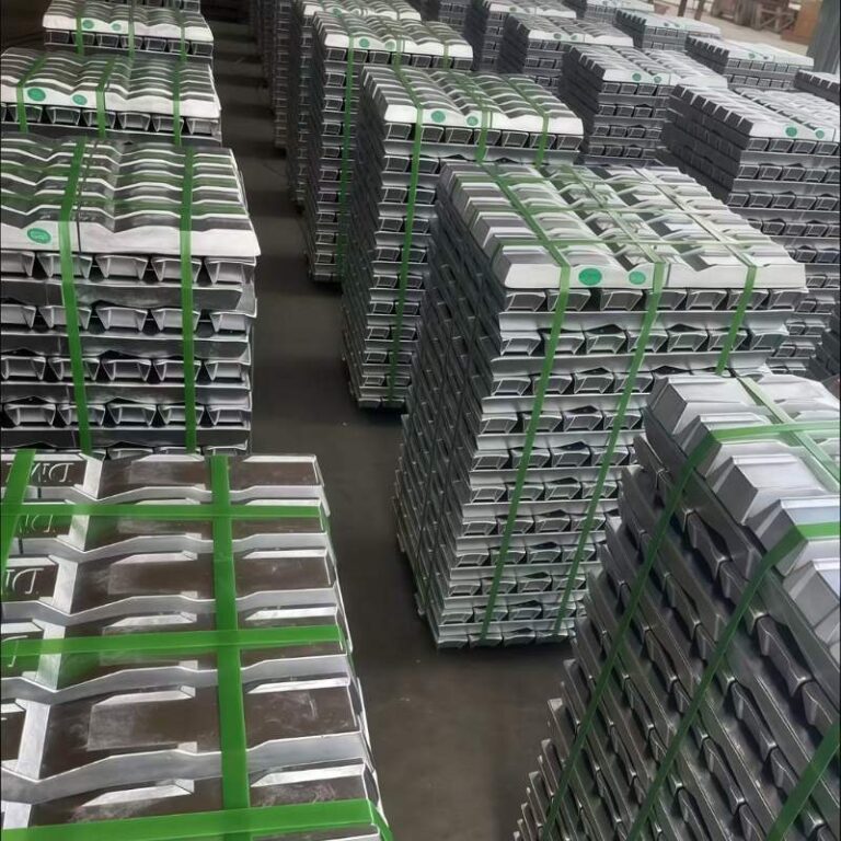
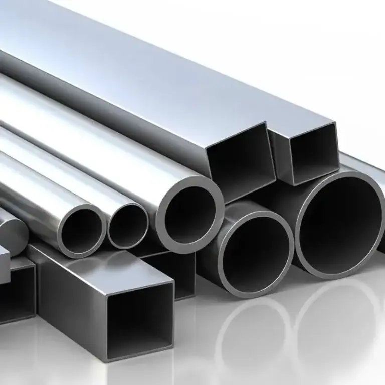
How To Choose The Right Materials For Aerospace CNC
Material selection in aerospace CNC machining defines accuracy, weight, and cost. Aluminum alloys (6061, 7075) cut efficiently, ideal for wing structures. Titanium Ti-6Al-4V offers ~900 MPa strength and is 45% lighter than steel, while Inconel 718 withstands >700°C but is hard to machine. PEEK, ULTEM, and CFRP are used for insulation and lightweight interiors. Balancing process–material–cost determines final performance and efficiency.
Materials Suitable For Aerospace CNC Machining
| Material Category | Representative Materials | Mechanical Properties | Machining Characteristics | Typical Applications |
| Aluminum Alloys (6xxx / 7xxx Series) | 6061: Yield strength ~276 MPa7075: Yield strength ~503 MPa | Lightweight, high strength | High-speed cutting 400–600 m/min, excellent machinability | Wing spars, fuselage structures, support brackets |
| Titanium & High-Temperature Alloys (Stainless, Inconel) | Ti-6Al-4V: Tensile strength ~900 MPa, 45% lighter than steelInconel 718: Heat resistance >700°C | High strength, heat and corrosion resistance | Machinability <20% of aluminum, high tool wear | Turbine blades, engine casings, landing gear |
| High-Performance Polymers & Composites | PEEK, ULTEMCFRP (Carbon Fiber Reinforced Polymer) | Heat resistant, flame retardant, lightweight | CFRP requires diamond-coated tools to prevent delamination | Cabin insulation, ducts, seat tracks, interior parts |
Balancing Process–Material–Cost
Material Cost vs. Performance Trade-Off
Titanium components typically cost 2–3× more than equivalent aluminum parts due to higher raw material prices and difficult machinability.
However, titanium’s superior strength-to-weight ratio (~900 MPa tensile strength, 45% lighter than steel) directly translates to fuel savings of 3–5% per flight on long-haul aircraft.
For airlines operating 1,000+ flights annually, this can reduce fuel expenses by millions of dollars per year.
Application-Based Material Allocation
Aluminum Alloys (6061, 7075): Used for non-critical components like seat brackets, interior supports, and secondary structures. They cost less, machine faster (cutting speeds of 400–600 m/min), and reduce cycle time by up to 30%.
Titanium (Ti-6Al-4V): Reserved for safety-critical areas like engine mounts, landing gear joints, and turbine parts, where failure would be catastrophic. The additional cost is justified by safety and regulatory compliance.
This selective allocation optimizes the material–process–cost triangle, ensuring both affordability and reliability.
Machining Process and Tooling Costs
Titanium and superalloys (e.g., Inconel 718) have a machinability index <20% of aluminum, meaning cycle times are 4–5× longer, and tool wear is significantly higher.
Specialized cutting tools with coatings like TiAlN or diamond-like coatings are required, increasing tooling costs by 50–100% compared to machining aluminum.
On the other hand, aluminum machining is highly cost-effective, with lower tool consumption and shorter setup times.
Lifecycle Cost and ROI Considerations
Although titanium increases initial manufacturing cost, the lifecycle ROI is positive because it improves aircraft fuel efficiency, durability, and part longevity.
For instance, titanium landing gear struts can extend service intervals by 20–30%, reducing downtime and MRO (Maintenance, Repair, Overhaul) expenses.
Aluminum brackets may require more frequent replacement but are economical in non-critical zones, balancing overall project cost.
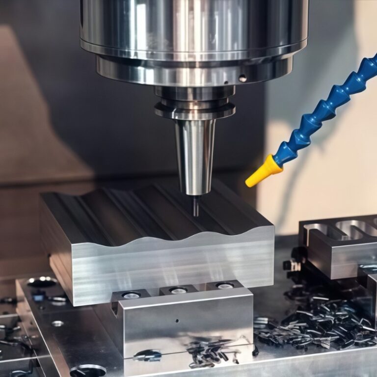
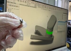
What Are The Processes In Aerospace CNC Machining
Aerospace CNC machining follows a precise digital chain—CAD to CAM, digital twin simulation, and AI-assisted programming that cuts cycle times by 30–50%. Core processes include 3/4/5-axis milling for structures and turbine parts, CNC turning for shafts and fasteners, and mill-turn machines that save up to 50% in cycle time. EDM and waterjet handle hard alloys and composites, while hybrid additive-subtractive machining reduces material waste by 20–40%. Advanced fixturing, probing, and thermal compensation ensure micrometer-level repeatability.
CAD → CAM → Digital Twin → Programming
CAD Modeling (Computer-Aided Design)
Aerospace CNC machining begins with CAD modeling, typically using software like CATIA or SolidWorks.
Engineers build precise 3D geometric models that define shape, assembly relations, and functional features.
Studies show that over 80% of part costs are determined during the design phase, meaning CAD accuracy directly drives manufacturing success.
CAM Conversion (Computer-Aided Manufacturing)
The CAD model is imported into CAM platforms such as NX, Mastercam, or Autodesk Fusion 360.
CAM generates toolpaths, optimizes cutting parameters, and manages tool libraries.
Advanced strategies like High-Speed Machining (HSM) and dynamic toolpaths can increase productivity by 20–30% while reducing tool wear.
Digital Twin Simulation
Before machining, digital twin simulations validate toolpaths in a virtual environment.
The simulation replicates machine, tool, and workpiece interactions to detect collisions, interferences, or thermal deformations.
Industry data shows digital twin adoption can cut trial-cut time by 40% and improve tool utilization by 20%.
For complex 5-axis parts like turbine blades, digital twins optimize angles and feeds, reducing rework rates.
CNC Programming (G/M Codes)
Once validated, CAM exports G/M codes, the machine-readable instructions for CNC controllers:
G01 : Linear interpolation
G02/G03 : Circular interpolation
M06 : Automatic tool change
Controllers like Fanuc and Siemens 840D execute these codes for micrometer-level accuracy.
With AI-assisted programming, cycle times can be reduced by 30–50%, and operator error rates drop by 40%+.
The CAD → CAM → Digital Twin → Programming workflow ensures a closed-loop manufacturing process from design to inspection.This process consistently achieves ±2–10 μm aerospace-grade tolerances.A real-world case showed that using this workflow for engine blade manufacturing reduced delivery time from 12 weeks to 8 weeks while improving yield rates by 15%.
Processes and Equipment
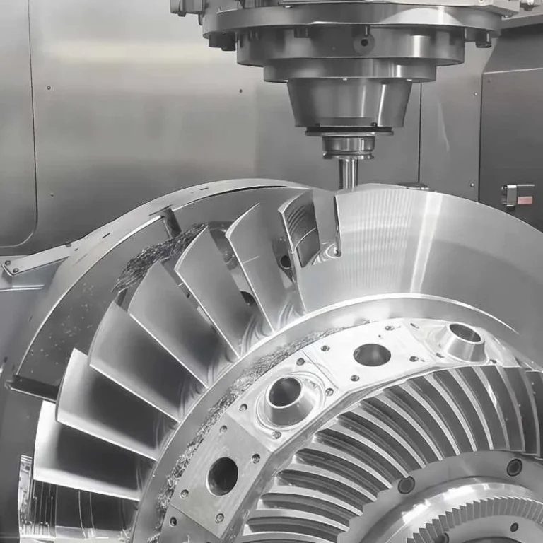
3/4/5-Axis Milling
Application: Critical for structural aerospace parts such as wing ribs, fuselage frames, and turbine blades.
Capability: 5-axis milling provides freedom to machine complex geometries in a single setup, reducing errors and achieving tolerances as tight as ±2–5 μm.
Impact: For turbine blades, multi-axis milling improves efficiency by 20–30% compared to traditional setups, while ensuring aerodynamic surface accuracy (Ra ≤ 0.2 μm).
CNC Turning
Application: Produces cylindrical parts like shafts, bushings, and threaded fasteners.
Precision: Aerospace turning can maintain concentricity within 0.005 mm, essential for high-speed rotating components.
Example: Jet engine shafts often require machining lengths up to 1.5–2 m while still maintaining straightness tolerance under 0.01 mm/300 mm.
Mill-Turn Machines
Application: Combines milling and turning operations in a single setup, ideal for gearbox housings, casings, and engine mounts.
Efficiency: Reduces handling and fixture changes, saving 30–50% in cycle time.
Case Study: An aerospace supplier reported reducing production lead time for landing gear joints from 6 weeks to 4 weeks by shifting to mill-turn centers.
EDM (Electrical Discharge Machining) & Waterjet Cutting
Application: Used for hard alloys (Inconel, titanium) and composites (CFRP, GFRP) where traditional cutting tools wear out quickly.
Performance: EDM can achieve surface finishes of Ra ≤ 0.1 μm and cut intricate cooling channels in turbine blades.
Advantage: Waterjet avoids heat-affected zones, critical for composite trimming, with accuracy up to ±0.05 mm on large panels.
Hybrid Manufacturing (Additive + Subtractive)
Application: Combines near-net-shape additive manufacturing (3D printing of titanium, Inconel, or AlSi10Mg) with CNC finishing.
Material Efficiency: Saves 20–40% of raw material, significant when machining high-cost alloys like titanium.
Real-World Data: NASA demonstrated that hybrid methods reduced titanium part buy-to-fly ratios from 12:1 to 3:1, cutting material waste by over 70%.
Tooling and Fixturing
“One-and-done” Setups
In aerospace manufacturing, large and complex parts such as wing spars or engine mounts must often be machined in a single setup.
Every re-clamping introduces ±5–10 μm of cumulative error, which can compromise structural integrity.
Using integrated fixturing that enables complete machining in one setup reduces errors and shortens overall cycle time by 20–30%.
Example: Boeing’s supplier network reports reducing wing rib machining cycle time from 18 hours down to 12 hours by adopting one-and-done setups.
Probing Systems
High-precision contact or laser probes are used for in-machine part measurement and automatic compensation.
This ensures workpiece alignment errors remain within ±2 μm.
Probing systems have been shown to cut first-article scrap rates by over 40%, raising first-pass yield (FPY) to ≥98%.
Vibration Damping
When machining tough materials like Inconel 718 or titanium alloys, tool–workpiece resonance can degrade surface finish (Ra > 1 μm).
High-damping fixtures (polymer-filled or liquid-damped) reduce vibration amplitude by 30–50%, allowing surface finishes of Ra ≤ 0.2–0.4 μm.
In turbine blade production, such damping fixtures also extend tool life by 25–35%, cutting tooling costs.
Thermal Compensation
Thermal expansion is a major error source in large aluminum or titanium aerospace structures.
For instance, aluminum has a linear expansion coefficient of 23 μm/m·°C—a 5°C variation can cause ±115 μm deviation over a 1-meter part.
Modern fixturing systems integrate sensors and compensation algorithms to correct thermal drift, maintaining accuracy within ±5 μm.
Flexible and Modular Fixtures
Aerospace manufacturing is increasingly high-mix, low-volume (HMLV), requiring frequent fixture changes.
Modular fixturing systems can be reconfigured in 30 minutes, compared to hours or days for traditional setups.
Widely used in satellite and UAV component machining, these systems raise Overall Equipment Effectiveness (OEE) by 8–12%.
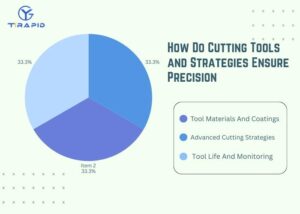
How Do Cutting Tools and Strategies Ensure Precision
In aerospace CNC machining, cutting tools and strategies directly shape accuracy, efficiency, and tool life. Carbide supports general use, while PCD/CBN handle composites and hardened steels. Coated tools, such as TiAlN, boost tool life by ~50% in Inconel. Advanced approaches like adaptive toolpaths, high-speed machining (20,000+ RPM), and MQL reduce heat, extending tool life by ~30%. With tool costs at 10–15% of total, wear monitoring lifts FPY from 93% to 98%.
Tool Materials And Coatings
Carbide
Carbide tools are the most widely used in aerospace CNC machining, especially for aluminum and stainless steel.
They operate reliably at cutting speeds of 200–600 m/min, making them highly efficient for large-batch production.
PCD / CBN
PCD (Polycrystalline Diamond) is ideal for trimming composites (e.g., CFRP), reducing delamination and burrs, with tool life 3–5× longer than carbide.
CBN (Cubic Boron Nitride) excels in hardened steels (>50 HRC), maintaining tolerances within ±0.005 mm even under heavy loads.
TiAlN-Coated Tools
Titanium Aluminum Nitride (TiAlN) coatings withstand cutting temperatures of >800°C, particularly in tough alloys like Inconel 718.
Tests show tool life can be extended by 40–50%, with cutting speed increases of about 20%.
Advanced Cutting Strategies
Adaptive Toolpaths
Maintain constant tool load by dynamically adjusting feed rates.
Reduce cycle times by 15–25% on structural aerospace components while minimizing tool breakage.
High-Speed Machining
Operates at spindle speeds of 20,000–40,000 RPM, commonly used for thin-walled structures and turbine blades.
Delivers ±0.01 mm accuracy and improves surface roughness to Ra ≤ 0.4 μm.
Minimum Quantity Lubrication (MQL)
Uses only 10–50 ml/min of oil mist, cutting coolant consumption by 80–90% compared to flood cooling.
Reduces tool temperature by 20–30%, extending tool life by around 30%.
Tool Life And Monitoring
Tooling Costs
In aerospace machining, tooling accounts for 10–15% of total manufacturing costs.
For hard-to-machine alloys like titanium and Inconel, tooling costs can exceed 20%.
Sensor-Based Monitoring
Sensors track vibration, power, and temperature in real-time to detect tool wear.
Data shows First Pass Yield (FPY) improved from 93% → 98% when sensor-based monitoring was adopted.
Predictive Maintenance
AI-driven wear analysis predicts tool life and prevents unexpected tool failure.
In turbine blade machining, predictive maintenance cut unplanned downtime by 20–25%, boosting equipment availability.
How Does Quality Control Guarantee Aerospace Standards
Aerospace CNC machining demands strict QC. FAI (AS9102) validates first runs, while SPC with CpK ≥ 1.67 ensures stability. Precision tools like CMMs (±2 μm) and laser scanning enable real-time checks. Compliance with AS9100D, ISO 9001, NADCAP is mandatory, forming the baseline for aerospace manufacturing reliability.
First Article Inspection & Statistical Process Control
First Article Inspection (FAI) is the first gateway before aerospace parts can enter mass production. Using AS9102 forms, it verifies that dimensions, geometry, tolerances, and surface finishes all match design intent. For example, in a landing gear project, hundreds of critical dimensions are documented, and even a ±5 μm deviation can result in rework or rejection.
Statistical Process Control (SPC) ensures production stability. Aerospace typically requires a CpK ≥ 1.67, meaning processes can consistently achieve 99.99% quality confidence. If CpK falls below 1.33, the process is flagged as high risk and must be corrected.
Metrology And In-Process Checks
Coordinate Measuring Machines (CMMs): High-end CMMs achieve ±2 μm precision, widely used for turbine blades, nozzles, and complex housings.
Laser Scanning & White-Light Interferometry: Capture millions of data points in seconds, essential for verifying freeform surfaces such as wing skins and aerodynamic test models.
On-Machine Probing Systems: Probes mounted on the CNC spindle measure tool offsets, thermal drift, and fixturing errors in real time. This enables closed-loop corrections, maintaining repeatability within ±3–5 μm. Shops using this approach report 30% scrap reduction and faster setup times.
Certifications And Standards
AS9100D: The aerospace-specific QMS standard that integrates ISO 9001 with additional safety, traceability, and risk management requirements.
ISO 9001: The foundation of global quality management, ensuring consistency and traceability.
NADCAP: A third-party accreditation for special processes such as welding, heat treatment, coating, and plating. Without NADCAP, suppliers are usually restricted to non-critical components.
ITAR / EAR Compliance: For defense and export-controlled projects, strict data and process security rules apply. Design files, machining records, and certificates must be tightly controlled, or suppliers risk fines and blacklisting.
How To Achieve Traceability And Data Security
In aerospace CNC machining, traceability and data security are as vital as tolerances. Each component carries batch codes and digital certificates, while MES/ERP systems with RFID and barcoding ensure full production history tracking. Compliance with ITAR/EAR, encryption, and restricted access safeguards CAD data and intellectual property, preventing leaks across the supply chain.
Digital Traceability
In aerospace CNC machining, digital traceability is a fundamental requirement. Every part must carry unique batch codes, Certificates of Conformance (CoCs), and a digital thread linking the entire process—from CAD design → process parameters → final inspection.
Under FAA and EASA standards, 100% of flight-critical parts must maintain full traceability so that in the event of an incident, the source of materials and machining records can be identified within 24 hours.
Implementing digital threads has been shown to reduce 30–40% of manual documentation time, lowering risks of missing records and ensuring compliance with aerospace audits.
MES/ERP Integration
Modern aerospace plants rely on MES (Manufacturing Execution Systems) and ERP (Enterprise Resource Planning) integration to manage the complete production lifecycle.
RFID and barcoding: Each part is tagged from raw stock to final inspection reports, ensuring transparent history at every stage.
Major OEMs like Boeing and Airbus require suppliers to retrieve part production and inspection records in under 10 minutes via ERP systems.
Data from industry surveys show that facilities using RFID + ERP integration experience a 60% reduction in material tracking errors and achieve audit pass rates above 95%.
Data And IP Security
Data security and intellectual property (IP) protection are as critical as machining tolerances. Any leakage of CAD files or process parameters can result in multi-million-dollar losses.
Regulatory compliance: All defense-related aerospace parts must comply with ITAR (International Traffic in Arms Regulations) and EAR (Export Administration Regulations). Violations can trigger multi-million-dollar fines and permanent exclusion from defense supply chains.
Encryption and access control: Industry best practice mandates AES-256 encryption for CAD/CAM data storage and transfer, with multi-factor authentication (MFA) for user access.
Auditing and monitoring: Aerospace manufacturers deploying end-to-end encryption with access logs have reported a 70% reduction in data breach risks, while also meeting NIST SP 800-171 and CMMC Level 2 compliance requirements.
How To Balance Prototyping vs. Mass Production
CNC machining enables aerospace companies to move quickly from concept to production, balancing speed, precision, and cost efficiency. With FPY >98%, OEE near 90%, and ROI horizons as short as 18 months for large OEMs, CNC remains indispensable for both prototyping and mass production in aerospace.
Rapid Prototyping & Engineering Validation
CNC machining plays a critical role in accelerating aerospace prototyping cycles.
Using 3–5 axis machines, functional prototypes can be delivered in as little as 3–5 working days, with tolerances maintained at ±0.005 mm.
This speed allows aerospace engineers to validate form, fit, and function early in the design cycle, reducing the risk of downstream redesigns.
Industry studies show that early CNC prototyping shortens the overall product development cycle by 20–30%, lowering design validation costs by up to $500k per program in large OEMs.
Scaling Into Mass Production
Transitioning from prototypes to large-scale production requires process stability and automation.
Modern aerospace-certified facilities achieve First Pass Yield (FPY) >98%, meaning almost every part passes inspection without rework.
Automation—such as robotic loading, in-machine probing, and adaptive toolpath corrections—has improved Overall Equipment Effectiveness (OEE) from 50–55% (manual operations) to 85–90% in automated lines.
This increase in OEE translates directly into higher throughput, more consistent quality, and 30–40% lower unit costs on high-volume programs like commercial jet engines and landing gear assemblies.
TCO And ROI Considerations
Aerospace machining involves high upfront capital investments, particularly in advanced multi-axis equipment.
A single aerospace-grade 5-axis CNC machining center typically costs $300,000–$500,000, excluding tooling, fixturing, and quality assurance systems.
For SMEs (small and medium-sized enterprises), the Return on Investment (ROI) horizon is often 3–5 years, as lower order volumes and slower utilization extend payback periods.
By contrast, Tier 1 OEMs and large defense contractors operating at higher throughput can recover investments within 18–24 months, thanks to economies of scale, long-term contracts, and automated workflows.
Advanced ROI models also factor in indirect savings: reducing rework rates by 50%, extending tool life by 20–30% with optimized strategies, and saving up to 20% in raw material costs via hybrid near-net-shape processes.
How to Choose the Right Aerospace CNC Supplier
Aerospace-grade CNC suppliers must combine micron-level precision, advanced 5-axis equipment, digital twin workflows, and robust certifications. True leaders prove themselves by sustaining OEE ≥85%, FPY ≥98%, and OTD ≥95%—the golden benchmarks that ensure reliability in one of the world’s most demanding industries.
Capability Matrix
When evaluating aerospace CNC machining suppliers, a capability matrix is the first checkpoint.
Minimum Achievable Tolerances: Top-tier suppliers consistently reach ±2–5 μm, while average shops often stop at ±20 μm.
Material Coverage: Aerospace-qualified vendors must handle a wide spectrum—aluminum alloys (6xxx/7xxx series), titanium alloys (Ti-6Al-4V), superalloys like Inconel 718, and high-performance polymers (PEEK, ULTEM).
Certifications: Certifications such as AS9100D, ISO 9001, ITAR, NADCAP (for special processes) are not optional, they are “entry tickets” to aerospace supply chains.
Equipment And Digitalization Maturity
Advanced machinery and digital capabilities directly impact precision and consistency.
Machine Mix: Leading suppliers often have >50% 5-axis machining centers, while lagging shops rely mostly on 3-axis machines.
In-Machine Probing Systems: Real-time error compensation can cut rework rates by 40%.
Digital Twin & Simulation: Virtual programming shortens programming/setup time by 30–50%, while reducing collision risks and scrap.
Quality And Delivery KPIs
Key KPIs define whether a supplier can sustain aerospace-level production.
OEE (Overall Equipment Effectiveness): World-class facilities maintain 85–90%, compared to the ~60% industry average.
FPY (First Pass Yield): Aerospace demands ≥98%, since rework can derail long-cycle programs.
OTD (On-Time Delivery): Qualified suppliers must keep ≥95%, critical for structural and engine components.
Digital Traceability: Advanced shops use MES/ERP with real-time KPI tracking, achieving minute-level production traceability.
FAQs
What Is An Aerospace CNC Machinist?
An aerospace CNC machinist operates and programs precision equipment to produce components that meet AS9100D and NADCAP standards. Typical tolerances are within ±0.005 mm, working with challenging materials such as titanium alloys and Inconel. Responsibilities include interpreting CAD/CAM data, executing in-process inspections, and ensuring every part complies with safety and airworthiness requirements.
How Is CNC Used In The Aerospace Industry?
CNC machining is widely applied to structural components, turbine blades, landing gear beams, and avionics housings. It ensures micron-level precision, for example, ±0.02 mm on Inconel 718 turbine blades. CNC also supports rapid prototyping, enabling design validation in 3–5 days. Compared to conventional processes, it offers superior repeatability, reduces human error, and supports both mass production and MRO (Maintenance, Repair, Overhaul).
What Is The Tightest Tolerance Achievable In CNC Aerospace Machining?
In my experience, aerospace machining can achieve tolerances as tight as ±2–5 μm on precision features using advanced 5-axis machines with in-process probing. Surface finishes on turbine blades can reach Ra 0.2 μm. These figures are significantly stricter than automotive standards, ensuring safe operation under extreme thermal and mechanical stresses.
Which Parts Are The Most Difficult To Machine In CNC Aerospace Machining?
Turbine blades and engine casings are the toughest due to superalloys like Inconel 718, which retain strength above 700°C. Machining efficiency drops below 20% compared to aluminum, and tool wear rates increase sharply. Deep-drilled landing gear beams made from 300M steel also demand stress-relief cycles and precise heat treatment control.
How Do I Ensure Suppliers Are Qualified?
I always start with their certifications: AS9100D, NADCAP (for special processes), and ITAR compliance. Then I review KPIs such as OEE >85%, FPY >98%, and OTD >95%. A qualified shop typically has at least 50% 5-axis capability, digital twin simulation, and proven traceability systems linking raw materials to final inspection.
Conclusion
CNC aerospace machining isn’t just about cutting metal—it’s about achieving precision with consistency. Success comes from balancing materials, tooling, processes, and digital systems, while ensuring certifications and supply chain resilience.From rapid prototypes to full-scale production, investing in skilled talent and advanced equipment prepares manufacturers not only for today’s strict standards but also for the next era of aviation and space exploration.What do you think? If you were designing a component for aerospace, would you prioritize tighter tolerances, lighter materials, or faster production?Welcom to message me,share your latest ideas!