Chromic Acid Anodizing (CAA, Type I) is a classical aluminum alloy surface treatment process that significantly improves corrosion resistance and bonding performance without altering part dimensions. This process is widely applied in aerospace, defense, and precision manufacturing, providing long-lasting durability for critical components. In this article, I will introduce the fundamentals of CAA, including pre-treatment, process flow, parameter control, quality inspection, engineering considerations, and safety measures, to help engineers and manufacturing enterprises fully master this essential technology.
What Is Chromic Acid Anodizing
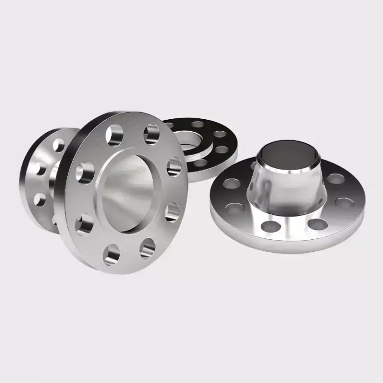
Chromic Acid Anodizing is an electrolytic process that forms a thin oxide film of 0.5–2.5 μm on aluminum alloys. Though thinner than sulfuric (5–25 μm) or hard anodizing (25–100 μm), when properly sealed it still delivers excellent corrosion resistance without affecting dimensional accuracy. It is commonly used in aerospace parts such as wing skins, landing gear, and components made from 2xxx series (e.g., 2024, high strength but poor corrosion resistance) and 7xxx series (e.g., 7075, excellent strength but corrosion sensitive) aluminum alloys.
Types Of Chromic Acid Anodizing (CAA, Type I)
Chromic Acid Anodizing (CAA, Type I) is categorized into several subtypes based on voltage, current density, and application needs. While all fall under Type I anodizing, their process parameters and use cases vary significantly.
Type I: Standard Chromic Acid Anodizing
Process Parameters: Operating voltage around 40 V, current density of 20–25 A/ft² (≈2.1–2.7 A/dm²), and bath temperature controlled at 35–40 °C.
Coating Thickness: Typically 0.5–2.5 μm (20–100 microinches).
Key Features:
Produces a thin but uniform oxide film that maintains tight dimensional tolerances.
When properly sealed (hot water, nickel acetate, or dichromate), provides corrosion resistance of 500–1000 hours in salt spray tests.
Applications: Aerospace components such as wing skins, landing gear parts, and fuel system hardware. Especially suitable for fatigue-sensitive high-strength alloys like 2024 and 7075.
Type IB: Low-Voltage Chromic Acid Anodizing
Process Parameters: Voltage reduced to 22–25 V, with lower current density to minimize stress.
Coating Thickness: Around 0.3–1.0 μm.
Key Features:
Creates thinner, more flexible coatings ideal for precision small parts.
Demonstrated fatigue performance improvements of 10–15% in high-strength alloys.
Applications: Precision fasteners, thin-walled components, and small parts requiring adhesive bonding.
Comparison Of CAA With Other Alternative Processes
| Process | Coating Thickness | Corrosion Resistance | Dimensional Accuracy | Environmental Performance | Common Applications |
| CAA (Type I) | 0.5–2.5 μm | Excellent | High | Poor | Aerospace, Defense |
| Sulfuric (Type II) | 5–25 μm | Good | Moderate | Better | Decorative Parts |
| Hard Anodizing (Type III) | 25–100 μm | Excellent | Low | Moderate | Wear-Resistant Components |
| TSA | 2–5 μm | Good | High | Excellent | Aerospace Alternative Process |
| TFSAA | 1–3 μm | Excellent | High | Excellent | European Aerospace Industry |
| BSA | 3–8 μm | Good | Moderate | Excellent | Adhesive Bonding Pre-Treatment |
Pre-Treatment For Chromic Acid Anodizing
In Chromic Acid Anodizing (CAA), pre-treatment quality largely determines the performance of the final oxide film. If the part surface contains oil, oxide scale, or if fixture contact is poor, it can easily lead to localized graying, blistering, or insufficient adhesion. To ensure a uniform and dense anodic layer, the entire pre-treatment process must be rigorously controlled.
Incoming Material Condition And Surface Roughness Requirements
Oxide Scale and Defects: The surface must be free from heavy oxide scale or mechanical damage. Standard practice involves alkaline etching + acid desmutting/activation to thoroughly remove surface contaminants.
Surface Roughness: For general parts, surface roughness should be controlled within Ra 0.6–0.8 μm to ensure adequate film adhesion.
Precision Components: Aerospace-grade 2xxx/7xxx series high-strength aluminum alloys often require chemical polishing or electropolishing, achieving Ra ≤ 0.4 μm to improve film uniformity.
Fixture And Racking Requirements
Material: Fixtures are usually made of titanium or aluminum, offering excellent corrosion resistance and stable conductivity.
Conductivity: Contact resistance should be ≤ 0.01 Ω to ensure uniform current distribution and avoid localized overheating.
Rack Point Design:
Must avoid critical functional surfaces, sealing areas, and conductive zones.
Rack marks should be limited to ≤1 mm, with controlled positioning and traceability.
Fixture Maintenance: Regular cleaning of fixture oxide layers is required to maintain low resistance and stable performance.
Masking And Identification Control
Masking Areas: Threads, precision mating surfaces, and conductive zones must be masked to prevent anodizing from affecting assembly or conductivity.
Common Methods:
Acid-resistant tapes with precision control of ±0.2 mm.
Silicone plugs or liquid masking agents, resistant to acids/alkalis, ideal for complex holes and internal cavities.
Identification: Parts should be marked outside masked areas using acid-resistant inks or laser engraving, ensuring batch traceability and process control.
A high-quality chromic acid anodizing layer depends on strict pre-treatment procedures. By controlling incoming material condition, surface roughness, racking fixtures, and masking/marking, manufacturers can significantly reduce defect rates and improve corrosion resistance, coating uniformity, and adhesion reliability.
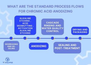
What Are The Standard Process Flows For Chromic Acid Anodizing
The standard process flow of chromic acid anodizing includes degreasing, alkaline etching/desmutting, anodizing, electrolyte control, pure water rinsing, sealing, drying, and packaging. By strictly following these parameters, the oxide film can achieve corrosion resistance of 500–1000 hours in salt spray tests, ensuring long-term stability of components in aerospace and military applications.
Degreasing And De-Oiling
Before chromic acid anodizing, degreasing and oil removal are the most critical first steps. If the oil residue exceeds the standard, it will directly lead to local voids in the film, insufficient adhesion, and even large-scale peeling.
Alkaline Cleaning (NaOH Solution)
Method:
Immersion in an alkaline cleaning solution (NaOH, 20–50 g/L) at 50–60 °C for 2–5 minutes effectively removes oils, grease, and light oxide scale, while also slightly etching the surface to improve adhesion for subsequent anodizing.
Control Points:
Regular monitoring of NaOH concentration and contamination levels.
Suitable for batch production and continuous cleaning lines.
Organic Solvent Cleaning
Common Solvents: Trichloroethylene, acetone, or alcohol.
Application: Ideal for precision components or parts with complex geometries and heavy oil contamination.
Process Requirements:
Solvent purity must be ≥99%, and the bath should be replaced frequently to avoid saturation.
Parts should move immediately to the next process to prevent recontamination.
Advantages: Capable of removing special lubricants and wax residues that alkaline cleaners cannot dissolve.
Ultrasonic Cleaning
Method: Ultrasonic cleaning uses the cavitation effect of sound waves in liquid, where microbubbles collapse and dislodge contaminants, typically performed at a frequency of 25–40 kHz, a temperature of 40–50 °C, and a cleaning time of 3–10 minutes.
Application: Ultrasonic cleaning is particularly effective for aerospace parts with microholes, blind holes, or internal cavities, ensuring thorough cleaning and reducing oil residue to ≤10 mg/m², thereby meeting strict aerospace requirements.
Quality Verification and Purpose
The Water-Break Test is used to verify surface cleanliness, where a clean part holds a continuous water film without beading, ensuring the surface is completely free of contaminants and ready for the formation of a dense, uniform oxide layer during subsequent anodizing.
Alkaline Etching , Acid Desmutting , Activation
Alkaline etching
Alkaline etching typically uses a NaOH solution concentration of 20–50 g/L at 50–60 °C for 1–5 minutes. Its primary purpose is to remove the natural oxide layer and residual stress layer on the aluminum surface, creating a more uniform substrate. The etching rate is generally 1–3 g/m²·min, which must be carefully controlled to prevent excessive etching that may cause dimensional deviations or surface roughness beyond specifications. For high-strength aluminum alloys (such as the 2xxx and 7xxx series), the etching time should not exceed 3 minutes to avoid pitting or excessive surface attack.
Acid Desmutting
After alkaline etching, residues such as Cu and Si often remain on the surface. These are removed using a solution of nitric acid (30–50 g/L) combined with fluorides (1–3 g/L). The desmutting process is typically controlled within 30–120 seconds to effectively remove impurities while avoiding excessive attack on the aluminum substrate. Prolonged exposure may increase corrosion rates and lead to surface roughness exceeding Ra 2.0 μm, compromising the quality of the subsequent anodic layer. This step is particularly critical for aerospace components, where residual impurities can significantly reduce coating uniformity and adhesion strength.
Activation
Following desmutting, activation treatment is required, usually via mild acid etching or electrochemical activation, to increase the surface energy of the aluminum substrate and enhance oxide film nucleation and bonding strength. Typical methods include weak acid activation (e.g., sulfuric acid 5–10 g/L) for 30–60 seconds. Activation can increase surface free energy by approximately 15–25%, thereby improving bonding strength. Adhesion tests (shear or peel strength) typically show an improvement of 10–20% after proper activation.
Anodizing
The stability of the anodizing process depends on precise control of electrolyte concentration, temperature, current density, and voltage. By operating under conditions of 35–40 °C, 20–25 A/ft², and 40 V (Type I) or 22 V (Type IB), and closely monitoring current behavior, it is possible to consistently produce 0.3–2.5 μm thick, dense, and uniform chromic acid anodized coatings. This ensures both corrosion resistance and dimensional stability, essential for aerospace and military components.
Electrolyte
The anodizing electrolyte typically consists of chromic acid at a concentration of 30–50 g/L. This range provides a dense, uniform oxide film while minimizing excessive substrate attack. The solution must remain chemically stable and be replenished regularly to maintain conductivity. In practice, the pH is controlled between 1.0–1.5, and contamination from dissolved metals (e.g., Al³⁺, Cu²⁺) should not exceed 5 g/L, otherwise, partial solution replacement or filtration is required to preserve corrosion resistance.
Temperature
Temperature is one of the most critical process variables. The recommended range is 35–40 °C:
Above 40 °C: Pore size increases, film becomes porous, and corrosion resistance can drop by 15–20%.
Below 35 °C: Growth rate slows, thickness uniformity declines, and cycle time may extend by 10–15%.
In aerospace production, temperature stability within ±1 °C is typically maintained by thermostatic water baths or cooling systems to ensure batch-to-batch consistency.
Current Density
The current density is generally set to 20–25 A/ft² (≈2.1–2.7 A/dm²). This ensures a dense oxide structure and reliable corrosion resistance.
< 2.0 A/dm²: Insufficient film growth (<0.3 μm).
> 3.0 A/dm²: Localized burning or microcracks may occur.
Industrial practice often combines controlled agitation of the electrolyte with current monitoring to maintain ion uniformity.
Voltage
40 V (Type I): Standard chromic acid anodizing, film thickness 0.5–2.5 μm, used for most aerospace and defense components.
22 V (Type IB): Low-voltage anodizing, film thickness 0.3–1.0 μm, ideal for precision parts and thin-walled components where dimensional changes must be minimized.
In high-precision applications, voltage control accuracy should be within ±0.5 V.
Process Control
During anodizing, the anodic current curve should show a smooth downward trend:
Stable curve: Indicates consistent oxidation and uniform film growth.
Fluctuations or sharp drops: Suggest poor electrical contact or electrolyte contamination.
For aerospace applications, online current monitoring and automatic data recording are widely used, combined with SPC (Statistical Process Control) to ensure thickness, uniformity, and corrosion resistance meet MIL-A-8625 Type I requirements.
Cascade Rinsing And Water Quality Control
By applying multi-stage cascade rinsing (≥3 stages), maintaining rinse water conductivity ≤50 μS/cm, and monitoring with pH and conductivity checks, manufacturers can ensure surfaces are completely free from contaminants. This step is essential to guarantee oxide layer integrity, maximize corrosion resistance, and ensure long-term reliability of anodized components.
Process Requirements
After chromic acid anodizing, residual acid or metal ions often remain on the part surface. If not thoroughly removed, these residues may cause secondary corrosion or compromise subsequent sealing and bonding performance. Therefore, multi-stage cascade rinsing (minimum three stages) is required. Each stage progressively dilutes the residual electrolyte, reducing surface ionic contamination to safe levels. Studies show that three-stage rinsing reduces residual ions by an additional 70–80% compared to single-stage rinsing. In aerospace manufacturing, multi-stage rinsing is a mandatory step in NADCAP audits.
Water Quality Standards
Rinsing water must be deionized or ultrapure water with conductivity of ≤50 μS/cm. For high-precision or military components, a stricter limit of ≤20 μS/cm is often imposed. If conductivity exceeds these thresholds, residual ions such as Cl⁻ or SO₄²⁻ may penetrate oxide pores, leading to pitting or delamination during service. Industrial systems typically employ online conductivity monitoring, coupled with automatic water replenishment and filtration cycles, to maintain stable long-term performance.
Inspection Methods
pH Testing: Rinse water should remain between pH 5.5–7.0. Deviations indicate possible acid or alkali contamination.
Conductivity Monitoring: Real-time sensors track water quality, with alarms triggered when conductivity exceeds preset values.
Water-Break Test: After rinsing, a clean surface should hold a continuous water film with no spotting. Presence of streaks or stains indicates incomplete cleaning.
Data Requirements
Residual acid content on part surfaces must be ≤1 mg/dm².
Cascade rinse tanks generally require partial replacement after 500–1000 L of process throughput to prevent accumulation of contaminants.
In aerospace components, insufficient rinsing can reduce corrosion resistance by 30–50% and significantly increase bonding or sealing failure risk.
Sealing And Post-Treatment
Hot Water Sealing: Performed at 90–100 °C for 30 minutes, this process forms boehmite (hydrated aluminum oxide) within the pores, effectively closing them and enhancing corrosion resistance.
Nickel Acetate Sealing: An environmentally friendly alternative that significantly reduces hexavalent chromium emissions while maintaining adequate corrosion protection.
Chromic Acid Sealing: A traditional method known for superior corrosion resistance, but its use is increasingly restricted due to environmental regulations.
Special Cases: For components intended for adhesive bonding, sealing is typically omitted to preserve the pore structure. This allows the adhesive to penetrate better, increasing shear strength by approximately 20–30%.
Drying And Packaging
By strictly controlling drying temperature (≤60 °C), drying duration (30–60 min), using chloride-free packaging materials, and implementing anti-static vacuum sealing with desiccants, manufacturers can effectively prevent film cracking and stress corrosion. These measures ensure chromic acid anodized parts maintain ≥12 months of protection during storage and transportation.
Drying Conditions
In the post-treatment stage of chromic acid anodizing, drying conditions are critical to ensuring coating integrity and long-term performance:
Temperature Control: Hot air must be maintained at ≤60 °C. Exceeding 65 °C may induce microcracks in the oxide film due to thermal stress, reducing corrosion resistance by 10–15%.
Duration: Typical drying time ranges from 30–60 minutes, adjusted based on part geometry and oxide thickness.
Airflow Uniformity: Air velocity should be 1–2 m/s, ensuring even drying across the entire surface and avoiding localized water spots that may cause secondary corrosion.
Monitoring: Infrared thermometers or contact sensors are recommended, keeping surface temperature deviation within ±2 °C.
Packaging Requirements
For aerospace and defense applications, packaging functions not only as storage protection but also as part of the corrosion prevention system:
Material Restrictions: Packaging materials must be free of chlorides, as chloride ions can cause Stress Corrosion Cracking (SCC) in high-strength aluminum alloys such as the 2xxx and 7xxx series.
Protection Level: Standard practice includes anti-static bags with vacuum sealing, preventing static discharge and moisture ingress. For critical parts, desiccants (e.g., silica gel, molecular sieves) are added to maintain humidity at ≤30% RH.
Storage Life: With proper vacuum sealing and moisture protection, components can achieve a shelf life of ≥12 months, and up to 18 months in controlled environments (20–25 °C, <50% RH).
Quality Verification: Post-packaging inspection may include chloride content testing (≤5 ppm) and vacuum integrity checks, ensuring compliance with aerospace and military standards.
Key Parameters And Process Control
By tightly controlling bath chemistry (CrO₃ 30–50 g/L, Al³⁺ ≤5 g/L), temperature (35–40 °C), current density (2.1–2.7 A/dm²), and voltage (22–40 V), combined with regular calibration and SPC monitoring, manufacturers can consistently achieve oxide films tailored for different applications—ensuring ≥500 hours of corrosion resistance or ≥30% improvement in adhesive bonding strength.
Bath Chemistry And Concentration Balance
The electrolyte composition plays a decisive role in chromic acid anodizing (CAA) performance:
Chromic Acid Concentration: Must be maintained at 30–50 g/L. Falling below 30 g/L reduces oxide density, lowering corrosion resistance by 20–30%, exceeding 50 g/L increases conductivity, raising energy consumption and accelerating bath degradation.
Aluminum Ion (Al³⁺) Content: Controlled at ≤5 g/L. Excess aluminum ions lead to gray discoloration, higher porosity, and a 15–25% reduction in corrosion life.
Monitoring Frequency: Comprehensive chemical analysis (titration or spectroscopy) should be performed weekly, followed by corrective dosing or bath replacement.
Temperature, Current Density, And Voltage Window
Temperature: Optimal at 35–40 °C, with a tolerance of ±1 °C.
Below 34 °C: Growth rate decreases by ~15%, causing incomplete oxide formation.
Above 41 °C: Films become porous and less corrosion-resistant, reducing performance by ~20%.
Current Density: Maintained at 20–25 A/ft² (≈2.1–2.7 A/dm²).
Too low (<2.0 A/dm²): Incomplete oxide coverage, shortening corrosion life by ~30%.
Too high (>3.0 A/dm²): “Powdering” effect occurs, leading to brittle, weak coatings.
Voltage Settings:
40 V (Type I standard) → film thickness 0.5–2.5 μm, suitable for general aerospace parts.
22 V (Type IB low-voltage) → film thickness 0.3–1.0 μm, ideal for precision parts where tight tolerances are required.
Film Thickness And Pore Structure Targets
Adhesive Bonding Applications: Film thickness 0.5–1.0 μm, with porosity >15%, allowing resin penetration. Tests show shear strength increases by 20–30% compared to unsealed surfaces.
Corrosion Resistance Applications: Film thickness 1.5–2.5 μm, porosity <10%, capable of withstanding >500 hours in salt spray testing without pitting.
Equipment Measurement And Calibration
Rectifiers and Ammeters: Require semiannual calibration to maintain control precision within ±1%.
Sensors (temperature, pH, conductivity): Must be calibrated monthly. A deviation >±2% can result in thickness errors of ≥0.2 μm.
Data Logging: Adoption of SPC (Statistical Process Control) is strongly recommended, enabling real-time monitoring of temperature, current, and voltage, and ensuring full process traceability.
Quality Inspection And Verification
In chromic acid anodizing (CAA, Type I), quality verification requires both non-destructive testing (NDT) and destructive testing to ensure process stability and batch-to-batch consistency. A structured inspection system guarantees that components meet the stringent requirements of aerospace, defense, and precision manufacturing.
Surface Coverage And Defect Evaluation
Standard Requirement: Surfaces should display a uniform gray appearance with ≥ 98% coverage, free from spots, pores, bubbles, or discoloration.
Inspection Method: Use optical microscopy (50–100×). Defects larger than 0.2 mm in diameter or exceeding a density of 1 defect/cm² are considered nonconforming.
Process Benchmark: In production, the nonconformance rate should remain ≤1%, higher values require investigation of pre-treatment or bath conditions.
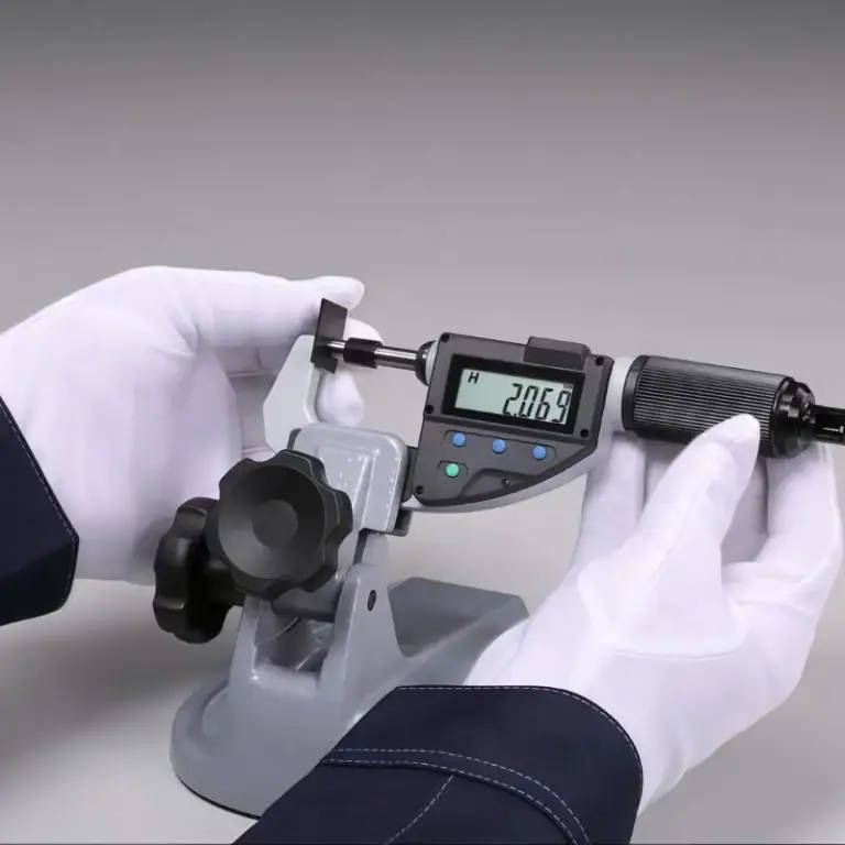
Coating Thickness Measurement
Film thickness is a critical parameter, requiring multiple measurement methods for cross-validation:
Eddy Current Method: ±0.05 μm accuracy, ideal for fast batch inspections.
Gravimetric Method: Laboratory standard, precision up to ±0.02 μm by weighing before and after stripping.
Cross-Section Microscopy: Using metallographic or SEM imaging for direct observation, highly accurate but destructive.
Target Ranges:
Adhesive bonding: 0.5–1.0 μm
Corrosion protection: 1.5–2.5 μm
Adhesion, Bonding Strength, And Corrosion Resistance
Adhesion/Bonding Strength: Lap shear strength must be ≥ 20 MPa, typically 30–40% higher than untreated aluminum.
Salt Spray Test (ASTM B117): ≥ 336 hours without pitting, high-end aerospace parts may reach 500–1000 hours.
EIS (Electrochemical Impedance Spectroscopy): Minimum impedance ≥ 10⁷ Ω·cm², indicating dense and corrosion-resistant films.
Electrical Resistance And Conductivity
For grounding and shielding applications, localized conductivity must be verified:
Grounding Resistance: ≤ 2.5 mΩ.
Testing Method: Four-point probe or micro-ohmmeter ensures contact reliability.
First Article, Periodic Testing, And Traceability
First Article Inspection (FAI): Comprehensive testing of film thickness, appearance, adhesion, and corrosion resistance to define the batch baseline.
Periodic Test Panels: At least weekly, standard test coupons are processed and validated to confirm bath stability.
Traceability: All test results must be linked to batch numbers and process parameters, in compliance with NADCAP or ISO 9001 quality management requirements.
What Are The Common Defects In The Chromic Acid Anodizing Process
The most frequent defects in CAA include discoloration, powdering, non-uniform coverage, and poor adhesion, each linked to solution chemistry, current density, pre-treatment, and fixturing design. By maintaining strict bath monitoring, controlling current density, ensuring proper fixturing, and implementing standardized reprocessing, defect rates can be reduced to <2%, thereby guaranteeing that anodized coatings meet stringent aerospace and defense standards.
Discoloration
Cause: Bath contamination or electrolyte aging, particularly when aluminum ion concentration exceeds 5 g/L or organic impurities accumulate.
Detection: Optical colorimetry or visual inspection, surfaces showing whitening or yellowing indicate electrolyte replacement is required.
Countermeasure: Weekly bath composition checks. Replace or replenish chromic acid when Al³⁺ ≥ 5 g/L or pH deviates from specification.
Powdering
Cause: Excessive current density (> 3 A/dm²) or over-thick coatings (> 3 μm) that create porous, brittle oxide films.
Appearance: Surface film detaches easily as powder when rubbed.
Countermeasure: Maintain film thickness within 0.5–2.5 μm for Type I. Monitor anodizing current curve—large fluctuations indicate poor contact or solution contamination.
Non-Uniform Coverage
Cause: Poor electrical contact from racks (contact resistance > 0.05 Ω) or complex part geometry leading to uneven current distribution.
Appearance: Localized thin or bare areas.
Countermeasure: Use titanium or aluminum racks with contact resistance ≤ 0.01 Ω. Place rack points outside critical areas and optimize placement for uniform current flow.
Poor Adhesion
Cause: Incomplete pre-treatment, oil residue > 10 mg/m², or insufficient desmut.
Detection: Lap shear or peel testing, values below 20 MPa indicate failure.
Countermeasure: Repeat alkaline etch (NaOH 20–50 g/L, 50–60 °C, 1–5 min) and acid desmut (HNO₃ + fluoride, 30–120 s) to restore surface cleanliness.
Reprocessing Protocol
Steps:
Stripping: Remove defective film using alkaline stripping (NaOH 50–100 g/L, 50–60 °C).
Rinsing: Cascade rinse with pure water (conductivity ≤ 50 μS/cm).
Re-anodizing: Resume anodizing with standard parameters.
Limitations: Parts should not exceed two reprocessing cycles, as repeated treatments increase surface roughness and reduce fatigue strength.
Production Line Considerations In Chromic Acid Anodizing
Production line performance in chromic acid anodizing depends not only on process accuracy but also on rack handling efficiency, bath regeneration, preventive maintenance, and environmental compliance. By adopting strict bath monitoring, effective regeneration, and robust waste treatment, manufacturers can keep defect rates below 2%, achieve consistent coating quality, and improve overall cost-effectiveness and sustainability.
Cost And Takt Time
Rack Changeover Efficiency: The time required for part mounting and electrical contact accounts for 15–25% of the total cycle. Optimized rack design and secure contact points can reduce changeover time to 2–3 minutes per part, lowering unit cost.
Bath Replacement Impact: Unit costs may fluctuate by 15–20% depending on electrolyte replacement. For example, a 1000 L bath replacement (including chemicals and treatment) can cost $3,000–$5,000, which becomes significant in high-volume production.
Bath Lifetime And Regeneration
Replacement Cycle: Traditionally, the chromic acid bath is replaced every 3–6 months to maintain chemical balance and coating quality.
Regeneration Strategy: By combining online filtration and chromic acid replenishment, bath life can be extended to 9–12 months. Data show that implementing regeneration reduces defect rates by ~30% and lowers unit costs by 10–15%.
Equipment Maintenance
Daily Checks: Pumps, pipelines, and rectifiers must be monitored to ensure current fluctuations remain within ±2%.
Weekly Cleaning: Filters, anode plates, and racks should be cleaned weekly to prevent contaminant buildup and ensure even current distribution.
Annual Calibration: Rectifiers, temperature control systems, and sensors must be calibrated annually to guarantee temperature stability within ±1 °C and current density deviation ≤ 0.05 A/dm².
Wastewater And Exhaust Treatment
Hexavalent Chromium Reduction: Waste liquid must undergo chemical reduction (e.g., sodium bisulfite or ferrous salts) to convert hexavalent chromium (Cr⁶⁺) into trivalent chromium (Cr³⁺), followed by precipitation and filtration. Post-treatment discharge must meet limits of ≤ 0.1 mg/L Cr⁶⁺, in line with global environmental regulations.
Exhaust Gas Treatment: Acid mist should be captured with local ventilation and scrubber towers at efficiencies ≥ 95%, reducing operator and community exposure risks.
Compliance: Facilities must comply with RoHS, REACH, and NADCAP requirements, with third-party audits conducted regularly to ensure environmental and occupational safety.
Industry Standards And Reference Guidelines For Chromic Acid Anodizing
Chromic Acid Anodizing is not only a technical process but also a regulated compliance framework. Adherence to MIL-PRF-8625 Type I, NADCAP accreditation, SDS/SOP requirements, and traceable inspection documentation is critical to meeting the stringent quality and reliability demands of aerospace, defense, and high-precision manufacturing industries.
MIL-PRF-8625 Type I
Military Performance Specification widely adopted in aerospace and defense.
Defines critical requirements such as:
Coating thickness: 0.5–2.5 μm.
Corrosion resistance: ≥ 336 hours in salt spray tests without pitting.
Adhesion strength: shear strength ≥ 20 MPa.
Specifies strict control over surface preparation, anodizing conditions, and sealing methods, along with full documentation for customer or government audits.
NADCAP (National Aerospace And Defense Contractors Accreditation Program)
A global accreditation system covering the entire aerospace supply chain.
Requirements include:
Process control: bath chemistry, temperature, and current density must be continuously monitored and records retained for at least 3 years.
Testing and validation: first article inspection, periodic coupons, and failure analysis are mandatory.
EHS compliance: facilities must implement a hexavalent chromium management plan, including scrubbers, wastewater reduction systems, and periodic emissions monitoring.
SDS And Work Instructions (Safety Data Sheets & SOP/WI)
Each chemical used (chromic acid, nitric acid, fluorides, etc.) must have a corresponding Safety Data Sheet (SDS) detailing hazard classification, first aid measures, storage requirements, and disposal procedures.
Production lines must follow standard operating procedures (SOP/WI) covering PPE usage, process parameters, and emergency actions.
Operators are required to undergo annual EHS training to ensure compliance and safety awareness.
Inspection Records And Customer/OEM Audits
All process data and inspection results must be fully traceable, including coating thickness, corrosion resistance, adhesion, and electrical resistance.
OEM and customer audits typically review 12 months of batch records, ensuring documentation completeness and compliance.
Aerospace OEMs such as Airbus and Boeing often require additional process capability indices (e.g., Cpk ≥ 1.33) to quantify and verify process reliability.
What Are The Application Areas Of Chromic Acid Anodizing
Chromic Acid Anodizing is widely applied in aerospace, defense, automotive, electronics, and medical industries. Its thin yet durable coatings (0.5–2.5 μm) provide corrosion resistance, bonding strength, dimensional stability, and biocompatibility, making it essential for critical aluminum components requiring long-term reliability and strict tolerance control.
| Industry | Typical Parts/Components | Application Objectives | Notes |
| Aerospace | Wing skins, landing gear, engine bay doors, satellite structures | Corrosion resistance, bonding base, dimensional accuracy | CAA is most widely applied in aerospace, compliant with MIL-PRF-8625 Type I and NADCAP standards, coating thickness 0.5–2.5 μm. |
| Defense | Rocket casings, missile sections, military electronic housings | Corrosion resistance, fatigue life retention | Thin CAA coatings maintain the fatigue performance of high-strength aluminum alloys (2xxx, 7xxx series). |
| Automotive | High-performance frames, engine parts, structural aluminum components | Corrosion protection, paint adhesion | Less common than aerospace, but increasingly used for lightweight, corrosion-critical components. |
| Electronics | Electrical connectors, heat sinks, shielding housings | Insulation, corrosion protection | Thin coatings (0.5–1.0 μm) applied, with conductive areas preserved through masking techniques. |
| Medical Devices | Surgical instrument housings, imaging equipment frames | Corrosion resistance, biocompatibility | Uniform, stable coatings ensure long-term reliability in medical environments. |
FAQs
Is Chromic Acid Anodizing Better Than Sulfuric Acid?
In my experience, chromic acid anodizing (CAA, Type I) is superior for precision parts. Its oxide layer is only 0.5–2.5 μm, compared to 5–25 μm for sulfuric acid anodizing (Type II). Despite the thinner coating, properly sealed CAA achieves equal or better corrosion resistance while avoiding dimensional changes. This makes it especially effective for aerospace components where fatigue life and strict tolerances are critical.
How Thick Is Chromic Acid Anodizing?
Chromic acid anodizing typically produces a coating thickness of 0.5–2.5 μm, much thinner than sulfuric or hard anodizing. In aerospace applications, I often control Type I coatings within 1.0–1.5 μm to balance corrosion resistance with dimensional accuracy. This thin layer is ideal for tight-tolerance assemblies like landing gear or wing skins, ensuring both durability and precision without altering critical fits.
What Is The Difference Between Hard Anodizing And Chromic Acid Anodizing?
Hard anodizing (Type III) produces coatings of 25–100 μm, offering excellent wear resistance but causing dimensional changes. In contrast, chromic acid anodizing forms a much thinner layer of 0.5–2.5 μm, mainly providing corrosion protection and strong bonding surfaces. I use CAA for aerospace precision parts where fatigue resistance and dimensional control are essential, while hard anodizing is reserved for high-wear applications such as cylinders, pistons, or sliding components.
What Metals Are Suitable For Chromic Acid Anodizing?
Chromic acid anodizing is most suitable for aluminum and its alloys, especially 2xxx (copper-based high-strength, e.g., 2024) and 7xxx (zinc-based ultra-high strength, e.g., 7075). I often use CAA on aerospace alloys where fatigue life and corrosion resistance are both crucial. Magnesium and steel are not suitable, while titanium may require alternative anodizing methods. CAA ensures both corrosion protection and bonding performance without compromising structural integrity of aluminum components.
Is Chromic Acid Anodizing Permanent?
Chromic acid anodizing is highly durable but not entirely permanent. The oxide layer can be degraded in acidic or alkaline environments and may wear over time. However, with proper sealing, I have seen aerospace parts last 10–20 years without corrosion. While the anodized coating “grows” from the base aluminum and is difficult to remove mechanically, it can be stripped by acid solutions or eroded under extreme service conditions.
Conclusion
Chromic acid anodizing is a classic process that balances process stability, dimensional accuracy, and corrosion resistance. It remains an irreplaceable, critical surface treatment method in aerospace, military, and precision manufacturing. With tightening environmental regulations, alternative processes such as TFSAA are emerging, but CAA remains one of the most reliable solutions in engineering practice. In your work, have you also encountered the challenge of meeting environmental regulations while ensuring corrosion resistance?Share your experiences and insights in a private message. Let’s explore the future trends in aluminum alloy surface treatment.