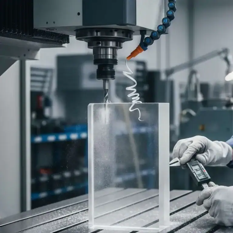
Ceramic CNC machining is an advanced process that allows for the precise shaping and production of ceramic materials. Due to their exceptional hardness, brittleness, and unique properties, ceramics require specialized machining methods to achieve high accuracy and precision. I will explore the characteristics of ceramic materials, the machining processes used, and the various advantages and challenges faced during the machining of ceramics.
What Is Ceramic CNC Machining
Ceramic CNC machining uses computer-controlled tools to shape ultra-hard, heat-resistant, and chemically stable ceramics. Although more challenging than metal machining, it enables high-precision parts for electronics, medical, semiconductor, and aerospace applications.
How Does Ceramic CNC Machining Work
Ceramic CNC machining removes material using diamond tooling, controlled toolpaths, and low-stress cutting strategies. Because ceramics are extremely hard (1500–2800 HV) and brittle, the process focuses on minimizing mechanical and thermal shocks.
Diamond Tool Cutting Mechanism
Ceramics require PCD, CBN, or diamond-coated tools.
Typical depth of cut: 0.05–0.3 mm
Real-time wear monitoring is essential to avoid chipping.
Low-Stress Machining Strategy
Feed rate: 0.02–0.05 mm/rev
Spindle speed: 12,000–24,000 rpm
Smooth toolpaths to prevent stress concentration and micro-cracks
Thermal Management
Ceramics crack easily from thermal shock.
Air blast or mist lubrication
Keep temperature between 20–80°C
Advanced Fixturing
Vacuum chucks, viscoelastic pads, and hydrostatic systems distribute force evenly and prevent fractures.
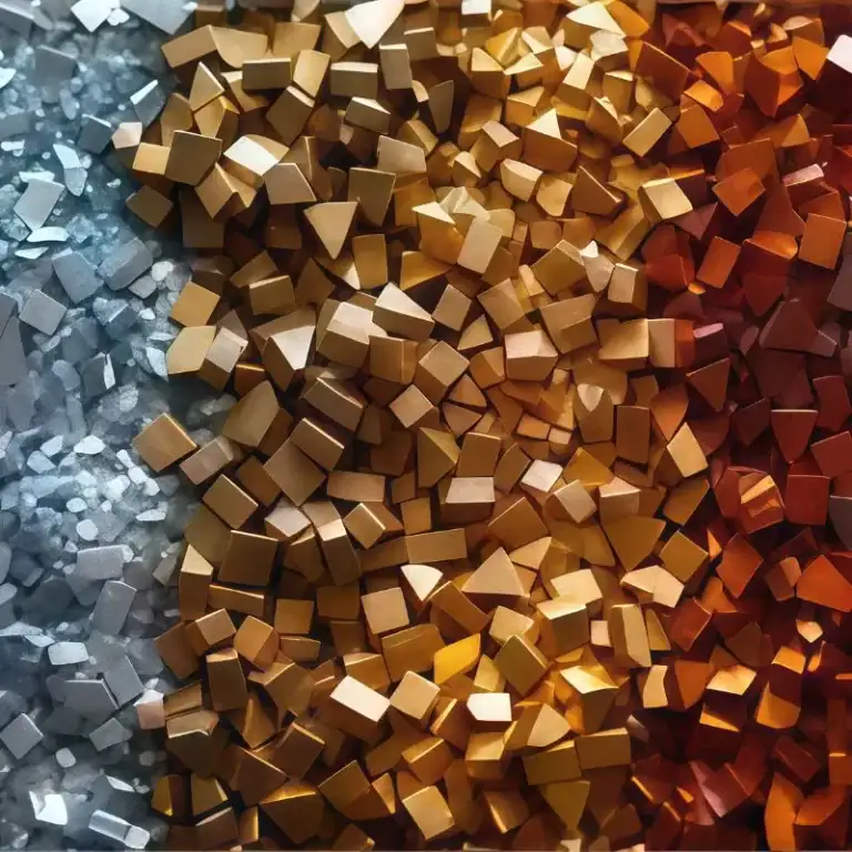
Common Ceramic Materials And Their Properties
| Ceramic Material | Thermal Conductivity (W/m·K) | Thermal Expansion Coefficient (µm/m·K) | Hardness (Vickers HV) | Wear Resistance | Electrical Insulation | High-Temperature Stability |
| Aluminum Nitride (AlN) | 170-200 | 4.5-5.0 | 15-20 | High | Excellent (Dielectric Strength ~15 kV/mm) | Excellent (up to 1000°C) |
| Alumina (Al2O3) | 20-30 | 7.0-8.0 | 180-220 | Excellent | Good (Electrical Insulator) | High (up to 1650°C) |
| Silicon Nitride (Si3N4) | 30-35 | 3.0-3.5 | 1200-1300 | Excellent | Good (Electrical Insulator) | Exceptional (up to 1400°C) |
| Mullite | 5-10 | 3.2-4.5 | 1000-1200 | Moderate | Good (Electrical Insulator) | High (up to 1700°C) |
The Impact Of Different Ceramic Material Properties On Machining
Each ceramic material’s unique properties significantly influence the machining process, determining the methods, tools, and parameters required to achieve optimal results. Here’s how different properties impact machining:
Aluminum Nitride (AlN) and Silicon Nitride (Si3N4)
Thermal conductivity: AlN has a thermal conductivity of 170-200 W/m·K, and Si3N4 has 30-35 W/m·K. These high thermal conductivity values allow heat dissipation, which is beneficial in electronic applications but also requires careful thermal management during machining.
Hardness: AlN (Vickers hardness: 1800 HV) and Si3N4 (Vickers hardness: 1200-1300 HV) are both very hard materials, making them tough to machine. Specialized tools, such as diamond-coated tools or PCD (polycrystalline diamond), are necessary to withstand the hardness and reduce wear on the tools.
Machining parameters: To avoid excessive tool wear, high spindle speeds (typically above 20,000 RPM) and low feed rates (10-50 mm/min) are used. These settings minimize thermal stress and ensure precise cuts without damaging the material.
Alumina (Al2O3) and Mullite
Brittleness: Both alumina and mullite are more brittle compared to AlN and Si3N4. Alumina has a Vickers hardness of 180-220 HV, while mullite ranges from 1000-1200 HV. Their brittleness makes them more susceptible to cracking and chipping under stress.
Machining parameters: To reduce the risk of cracking, lower spindle speeds (1,000-3,000 RPM) and reduced feed rates (10-30 mm/min) are typically used. These settings help minimize mechanical forces that could lead to fractures.
Cooling systems: Proper cooling is essential for alumina and mullite. Water-based coolants or mist cooling systems help dissipate heat during machining, preventing thermal buildup that could cause surface defects or cracking.
How To Choose The Right Ceramic Material
Structural Ceramics (Strength, Wear, Heat Resistance)
Alumina, Zirconia, Silicon Carbide, Silicon Nitride
Alumina: electrical insulation, wear resistance
Zirconia: highest fracture toughness (9–10 MPa·m½), ideal for implants
SiC: 1600°C resistance, used in semiconductor and aerospace
Si₃N₄: excellent high-temperature strength
Functional Ceramics (Thermal, Electrical, Chemical Performance)
AlN, BN, Quartz, Talc ceramics, Cordierite, Titanates
AlN: 170–260 W/mK thermal conductivity
BN: natural lubricity, used in plasma and high-temp fixtures
Quartz: ultra-low thermal expansion
Cordierite/Talc: used in heaters, insulation parts
Machinable Glass Ceramics (Prototyping, Fixtures)
Macor, Mycalex, Glass ceramics
Machinable with carbide tools
Ideal for ±0.02–0.05 mm tolerances
Best for prototypes, small-batch fixtures, and insulation parts
Material Selection Principles by Application
| Industry | Key Requirements | Recommended Ceramics |
| Electronics/Semiconductors | Insulation, thermal stability | AlN, Quartz, SiC |
| Medical | Biocompatibility, toughness | Zirconia |
| Aerospace | High-temp strength | Si₃N₄, SiC |
| Defense/Wear | Extreme hardness | SiC, Al₂O₃ |
| Prototyping/Fixtures | Machinability | Macor, Mycalex |
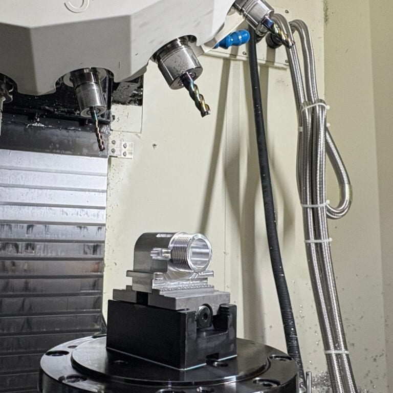
What Is the Complete Process Of Ceramic CNC Machining
The ceramic CNC machining process includes material preparation, engineering design, CAM programming, rough-to-finish machining, cooling management, post-processing, and final inspection. Each step must precisely control force, heat, and tool wear to ensure dimensional accuracy and defect-free ceramic parts.
Material Preparation & Blank Forming
Ceramic performance is largely determined during forming.
Hot Pressing
Sintering is performed under high temperature and uniaxial pressure, resulting in high density and high mechanical strength.
Suitable for: SiC, B4C, and other hard-to-sinter ceramics.
Features: Excellent dimensional stability but the highest processing cost.
Cold/Hot Isostatic Pressing (CIP / HIP)
Applies uniform pressure from all directions to compact ceramic powders.
Produces blanks with consistent density, ideal for high-precision CNC machining.
HIP (Hot Isostatic Pressing) is used for final strengthening to improve toughness and overall mechanical strength.
Pre-sintering (White State)
Moderate strength with hardness not yet fully developed.
This is the most economical stage for ceramic CNC machining due to low cutting resistance and extended tool life.
Fully Sintered
The material reaches its maximum hardness (e.g., zirconia HV 1200+, SiC HV 2500+).
Only diamond grinding, ultra-fine machining, or minimal material-removal techniques can be used.
Part Design & Engineering Review
Tolerance Planning
Typical tolerances of ±0.01 mm are common for zirconia and alumina.
High-precision components can achieve ±0.005 mm (requires precision grinding).
Avoid assigning tight tolerances to all surfaces, as this can increase manufacturing cost by 3–5×.
Geometric Dimensioning & Control
Flatness: 0.005–0.02 mm
Perpendicularity: 0.01–0.05 mm
Since ceramics cannot be “realigned” or plastically deformed, any deviation is irreversible.
Therefore, potential error sources must be anticipated during toolpath planning.
Tolerance Stack-Up Analysis
Applied to ceramic parts used in assemblies, such as semiconductor guide rails or medical sleeves.
Factors to consider: sintering shrinkage, grinding allowance, and inherent material warpage.
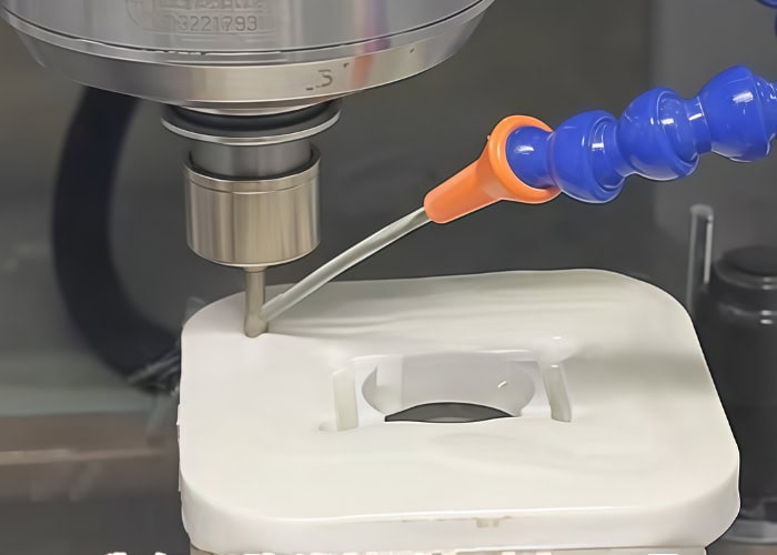
CAM Programming & Toolpath Planning
Rough Machining Toolpaths
High spindle speeds (12,000–20,000 rpm)
Small feed per tooth (0.02–0.05 mm/tooth)
Multiple light cuts, reducing step-over by 30–50% helps minimize edge chipping
Finishing Toolpaths
Use streamline toolpaths (constant engagement) to avoid sudden tool bite
Remove sharp internal corners and use radius transitions
Step-over controlled at 0.01–0.02 mm to achieve Ra 0.4–0.2 μm surface finish
Toolpath Strategies
Helical ramp entry to avoid impact loading
Segment contour machining to reduce thermal stress
Layered machining for areas with insufficient support
Roughing, Semi-Finishing, And Finishing Segmentation
The high hardness and brittleness of ceramics make staged machining essential.
Roughing
Removes 60–70% of the material
Tools: Diamond-coated end mills
Typical depth of cut: <0.3 mm
Semi-Finishing
Removes the remaining 0.2–0.5 mm of stock
Objective: Ensure uniform load during the finishing pass
Commonly used for complex internal cavities or thin-wall structures
Finishing
Achieves final dimensions and surface quality
May include: fine grinding / super-finishing
Capable of reaching ±0.005 mm when combined with face grinding
Cooling And Lubrication Control
Due to ceramics’ low thermal conductivity, temperature management is far more critical than in metal machining.
Dry Cutting
Common for pre-sintered ceramics
Prevents thermal shock cracking
Air blasts remove ceramic dust and reduce secondary friction
Minimum Quantity Lubrication (MQL)
Recommended for finishing operations
Can reduce tool wear by 20–40%
Mist Cooling
Suitable for high-hardness ceramics (SiC / AlN)
Maintains machining zone temperature at 20–80°C
Prevents sudden cooling that may cause ceramic fracture
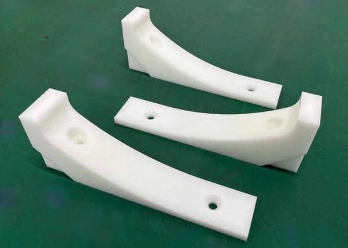
Post-Processing
Grinding
Diamond wheels deliver Ra 0.1 μm.
Polishing
Required for medical and optical ceramics.
Coating
Anti-wear or conductive coatings where needed.
Cleaning
Ultrasonic cleaning removes micro-debris.
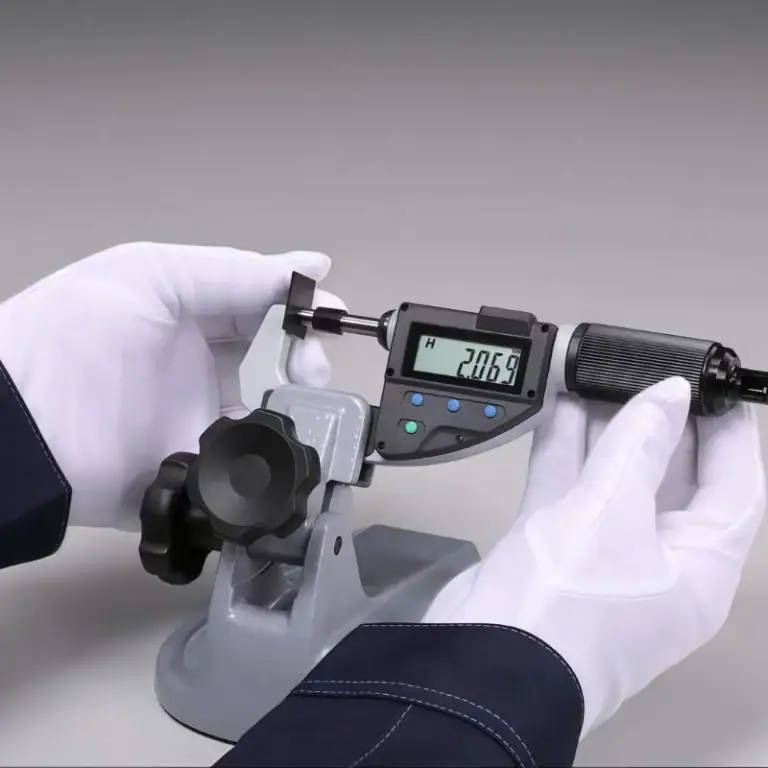
Final Inspection & Quality Control
CMM
±0.002 mm accuracy.
Form Measurement
Controls flatness, roundness, etc.
Surface Roughness
Ra 0.1–0.4 μm typical for high-quality ceramics.
What Are The Key DFM Considerations For Ceramic CNC Parts
Ceramics are extremely hard, brittle, and non-correctable once machined. Proper DFM planning—wall thickness, radii, tolerances, and structural simplification—greatly reduces chipping, machining steps, cost, and overall risk. The guidelines below help ensure your ceramic designs are manufacturable and reliable.
Recommended Wall Thickness, Chamfers, Fillets, And Minimum Feature Size
The brittle-fracture behavior of ceramics makes thin walls, sharp corners, and abrupt section changes high-risk features.
Minimum Wall Thickness
Alumina / Zirconia: ≥1.0–1.5 mm
Si₃N₄ / SiC: ≥1.5–2.0 mm
Fillets & Corner Design
Internal radii ≥R0.3–R0.5 mm improve crack resistance by 20–40%
External edges should include chamfers or ≥R0.2 mm
Minimum Feature Size
Ribs or posts: ≥0.8 mm
Narrow slots: ≥0.5 mm (depth-to-width ≤1:4)
Case: A semiconductor alumina guide cracked in roughing due to sharp corners, adding R0.5 mm eliminated the issue.
Hole, Slot, Thread, And Step Geometry Limits & Alternatives
These features carry the highest machining risk in ceramics.
Hole Diameter & Depth
Diameter ≥0.8 mm
Depth ratio ≤1:6
Use stepped holes or laser finishing for deep features
Threads Should Not Be Tapped Directly
Side loads easily cause cracking
Best practice: metal thread inserts (Helicoil / Keensert)
For coarse threads, use hybrid ceramic–metal assemblies
Slots & Steps
Slot width ≥0.6 mm
Step height ≥0.3 mm
Case: Replacing direct M3 tapping in zirconia with metal inserts improved strength by ~300% and extended service life tenfold.
Set Realistic Tolerances And Fit Grades To Avoid Over-Engineering
Tighter tolerances increase cost and failure rates exponentially.
Typical Tolerances
CNC machining: ±0.02–0.05 mm
Precision grinding: ±0.005–0.01 mm
Why Over-Tightening Should Be Avoided
Each 0.01 mm tightening can raise cost by 20–50%
Ceramics cannot be straightened or reworked
Fit Recommendations
Sliding fit: 0.01–0.03 mm clearance
Minimize the number of surfaces requiring grinding
Case: A part fully dimensioned at ±0.005 mm was redesigned, after relaxing 90% of dimensions to ±0.03 mm, cost dropped by 40%.
Structural Adjustments To Reduce Setups And Machining Steps
Ceramic components cannot be repaired once chipped, so fewer setups directly improve yield.
Design Recommendations
Consolidate machining surfaces into no more than two setups
Add reference flats and avoid unsupported features
Symmetrical geometry improves machining stability
Benefits
One fewer setup reduces cracking risk by 10–20%
Combined features reduce tolerance stack-up
Case: A ceramic valve seat originally requiring five setups was redesigned to two, improving first-pass yield from 82% to 97%.
Common Design Mistakes And Practical Improvements
Thin walls (<1 mm, high aspect ratio) → Add ribs or increase to 1.2–1.5 mm
Sharp internal corners → Replace with R0.5 mm
Direct ceramic threading → Use metal inserts
Unnecessarily tight tolerances → Apply precision only where functional
Deep, narrow slots → Use stepped or segmented slot designs
Case: A through-hole with 0.6 mm wall thickness cracked instantly, after increasing to 1.2 mm, the part machined successfully.
What Key Parameters Determine The Precision Of Ceramic CNC Machining
Ceramics exhibit extreme hardness, brittleness, and minimal thermal expansion, making machining precision highly dependent on tooling, machine rigidity, cooling, fixturing, and environmental stability. Even minor deviations can cause microcracking, edge chipping, or dimensional errors.
Tool Materials & Wear Control
With ceramic hardness ranging from HV 1200–2500, tool wear is the primary factor affecting precision.
Diamond tools
Ideal for zirconia, alumina, SiC, maintain <0.01 mm cutting-edge radius.
PCD (Polycrystalline Diamond)
Up to 3–5× tool life in volume production.
CBN
Suitable for high-temperature ceramics, less hard than diamond.
Balancing Cutting Speed, Feed, Depth Of Cut & MRR
Because ceramics fracture rather than plastically deform, light cutting is essential.
Typical parameter ranges:
Cutting speed: 300–800 m/min
Feed: 0.01–0.05 mm/tooth
Depth of cut: 0.05–0.3 mm
Lower MRR in finishing (reduced by 60–80%) yields surface roughness improvements from Ra 0.6 μm → 0.2 μm.
Spindle Speed, Machine Rigidity & Positioning Accuracy
High-precision ceramic machining requires:
Spindle: 12,000–24,000 rpm
Positioning accuracy: ±2–3 μm
High-stiffness frames to suppress vibration
If spindle runout exceeds 3–5 μm, unstable cutting leads to chipping.
Fixturing, Clamping & Vibration Control
Ceramics cannot withstand point loads, stress distribution is critical.
Recommended techniques:
Vacuum fixturing for thin or flat parts
Soft pads (silicone/PU) to reduce stress concentration
Uniform-pressure clamping keeping stress <5 MPa
Minimizing cantilever features
Vibration as small as 10–30 μm can cause irreversible ceramic damage.
Cooling & Lubrication Strategies
Ceramics are extremely sensitive to thermal shock.
Dry Cutting
Prevents sudden temperature gradients, ideal for white-stage ceramics.
MQL lubrication
Extends tool life 20–40%, stabilizes thermal input.
Mist cooling
Controls machining temperature within 20–80°C for SiC, AlN.
Above 80°C, microcrack probability sharply increases.
Environmental Temperature, Thermal Drift & Machine Calibration
Precision ceramics often require ±0.01 mm tolerances.
Shop temperature: 20 ± 1°C
Thermal drift: 1°C change → 1–3 μm error
Long-axis calibration with laser interferometry is essential
For zirconia and silicon nitride, the material is so dimensionally stable that machine drift becomes the dominant error source.
Toolpath Strategies
Correct toolpaths reduce chipping risk by 50–70%.
Step-down cutting
Helical ramp entry
Constant engagement toolpaths
Replacing sharp corners with radii
How Tolerance & Surface Roughness Requirements Constrain Parameters
Higher precision requires lower cutting forces and more controlled parameters.
| Requirement | Recommended Process |
| ±0.02–0.05 mm | Standard CNC |
| ±0.005–0.01 mm | Precision grinding |
| Ra < 0.2 μm | Diamond grinding/polishing |
How To Reduce Defects And Scrap Rates In Ceramic CNC Machining
Ceramics are extremely brittle, hard, and sensitive to thermal shock, making them prone to chipping, microcracks, and dimensional drift during machining. Achieving stable tolerances of ±0.01 mm—or even ±0.005 mm—requires systematic control of toolpaths, heat management, surface integrity, and upstream DFM design.
Reduce Brittle Fracture With Soft Entry, Ramp Cuts & Helical Interpolation
Ceramic fracture follows Griffith’s brittle failure mechanism, so impact loading must be avoided.
Effective strategies include:
Helical ramp entry – reduces vertical impact, chipping rate decreases 40–60%
Slope-based tool entry – stabilizes tool engagement
Constant engagement toolpaths – prevent sudden cutting force spikes
Use Precision Grinding & Polishing To Remove Subsurface Damage (SSD)
Surface smoothness does not equal structural integrity. SSD layers can propagate into functional cracks.
Solutions:
Diamond grinding – removes 20–80 μm of SSD
Ultrafine grinding – reduces SSD to <5 μm
Polishing to Ra ≤ 0.1 μm – improves fatigue life and insulation properties
For SiC cooling plates, SSD removal improved dielectric strength by 25–40%.
Control Thermal Stress With Segmental Cutting & Intermittent Cooling
Ceramics fracture when ΔT exceeds 80°C. Therefore heat management is crucial.
Recommended techniques:
Segmental cutting – limits instantaneous heat buildup
Pulsed cooling (2s air blast + 5s cutting) – reduces crack formation by 30%
MQL lubrication – enhances tool life and moderates temperature
Using pulsed cooling on alumina substrates reduced scrap rates from 9% to 2.1%.
Apply DFM Review During Design
Most machining defects originate in the design stage.
Key design rules:
Minimum wall thickness: ≥0.5–1.0 mm
Replace sharp corners with R0.3–0.5 mm radii
Support thin plates evenly
Verify hole spacing, slot geometry, and tool accessibility
A customer’s zirconia housing had a 30% scrap rate, after increasing inner corner radius to R0.5 mm, yield improved from 70% to 96%.
Build A Trial–Validation–Mass Production Process Optimization Loop
Ceramic machining requires iterative refinement—not one-time parameter setup.
Closed-loop workflow:
Trial Cut – evaluate chipping, tool load, temperature
Measurement – CMM, microscopy, SSD inspection
Tuning – adjust feed, speed, depth, toolpaths
Pilot Production – validate consistency before mass production
A professional ceramic machining supplier will also generate tool-life curves and Cp/Cpk capability reports to ensure long-term process stability.
What Are The Advantages And Limitations of Ceramic CNC Machining
Ceramics offer exceptional hardness, thermal stability, chemical resistance, and mechanical strength, making them ideal for aerospace, semiconductors, medical devices, and high-wear applications. Ceramic CNC machining achieves tolerances as tight as ±0.01 mm or even ±0.005 mm, but the material’s inherent brittleness and the process’s high technical demands also present significant challenges.
Advantages Of Ceramics CNC machining
Precision and Dimensional Accuracy
Ceramics deform very little during machining, enabling excellent tolerance control.
Typical tolerance: ±0.01 mm
With precision grinding: ±0.005 mm
Materials like zirconia and silicon nitride maintain stability even under heat and load
Exceptional Strength and Durability
Ceramics offer compressive strengths exceeding 2000 MPa, outperforming steel and aluminum.
Zirconia provides toughness similar to some metals
Si₃N₄ and SiC withstand high loads and rotational stress
Lifetime is 3–10× longer than metal components
Superior Wear Resistance
Typical hardness values:
Zirconia: 1200+ HV
Alumina: 1500 HV
SiC: 2500 HV (approaching diamond)
Ideal for high-friction components such as pumps, valves, nozzles, and semiconductor rails.
High Temperature Resistance
Ceramics maintain mechanical and dimensional stability at extreme temperatures:
SiC: up to 1600°C
Si₃N₄: widely used in turbine and high-load applications
Alumina: electrical insulation in high-temperature systems
Perfect for aerospace, energy, and vacuum environments.
Chemical Stability
Ceramics resist corrosion across the entire pH 0–14 range.
Excellent resistance to acids, alkalis, and solvents
Electrically insulating
Widely used in semiconductor, electronic, and chemical industries
Cost Efficiency
Although individual machining costs are higher, ceramics reduce long-term expenses:
Longer service life
Lower maintenance and downtime
Higher stability and fewer failures
Ideal for high-value industries such as medical, aerospace, and semiconductors.
Challenges In Ceramic CNC Machining
High Brittleness and Extreme Hardness
Ceramics have low fracture toughness, making them susceptible to:
Chipping
Microcracking
Catastrophic breakage
SiC and AlN require diamond tooling and highly controlled machining.
Thermal and Mechanical Stress Sensitivity
Ceramics are vulnerable to thermal shock:
Cracking occurs when ΔT exceeds 80°C
Poor thermal conductivity causes heat accumulation
Requires mist cooling, MQL, or pulsed airflow
Tool Wear and Equipment Requirements
Because ceramics are harder than most metals:
PCD, CBN, or diamond tools are mandatory
Machines must offer exceptional rigidity and precision
Tool wear is significantly faster
This results in higher equipment and tool investment.
What Are The Applications Of Ceramic CNC Machining
Ceramic CNC machining is widely used across aerospace, medical, electronics, automotive, and industrial sectors. With exceptional hardness, wear resistance, and electrical insulation, ceramic components perform reliably under high temperature, high load, and corrosive environments, making them ideal for demanding applications.
| Industry | Typical Applications |
| Aerospace & Defense | Turbine components, armor plates, insulating brackets |
| Medical & Dental | Zirconia dental implants, surgical tools, ceramic insulators |
| Electronics & Semiconductor | Wafer chucks, insulating substrates, ceramic heat spreaders |
| Automotive & New Energy | Sensor housings, sealing components, insulators |
| Industrial Equipment & Energy | Wear-resistant liners, pump/valve components, corrosion-resistant parts |
FAQs
Are Ceramics Difficult To Machine?
Yes, ceramics are difficult to machine due to their hardness and brittleness. For instance, materials like Aluminum Nitride (AlN) and Silicon Nitride (Si3N4) have Vickers hardness values ranging from 1200 to 1800 HV, which causes rapid wear on standard tools. This requires specialized equipment, such as diamond-coated tools, and precise machining parameters to prevent cracking. Additionally, ceramics are sensitive to thermal and mechanical stresses, making effective cooling and vibration control essential during ceramic CNC machining.
What Are The Methods Of Ceramic Production?
Ceramic production involves several methods, including dry pressing, extrusion, slip casting, and injection molding. For example, dry pressing is commonly used for producing dense parts, with pressures ranging from 100-200 MPa. Slip casting is ideal for creating complex shapes, utilizing liquid clay with particle sizes around 0.1-0.5 µm. Each method is selected based on the desired material properties, such as strength, porosity, and shape complexity, which are crucial for industries like aerospace and electronics.
How Are Engineering Ceramics Manufactured?
Engineering ceramics are typically manufactured through processes like dry pressing, sintering, and hot pressing. For example, dry pressing involves applying pressures of 100-200 MPa to form ceramic shapes. Sintering, at temperatures ranging from 1,200°C to 1,600°C, enhances material density and strength. Hot pressing uses temperatures up to 2,000°C combined with pressure to achieve high-density ceramics. These methods ensure that engineering ceramics, such as alumina or silicon carbide, meet the required mechanical properties for applications in aerospace, medical, and electronics industries.
Can Alumina Ceramic Be CNC Machining?
Yes, Alumina ceramic can be CNC machined. With a Vickers hardness of 180-220 HV, it is commonly used for precision components in industries like aerospace and electronics. CNC machining of Alumina requires diamond-coated tools due to its hardness. Typical machining speeds range from 1,000 to 3,000 RPM with feed rates of 10-50 mm/min. To prevent cracking, low cutting depths (0.1 mm or less) are used, and cooling systems are essential for maintaining tool life and part integrity during machining.
What Are The Benefits/drawbacks Of Using Ceramic Bearings?
Ceramic bearings offer excellent wear resistance, with a hardness of 1200-1300 HV for materials like Silicon Nitride (Si3N4), making them ideal for high-load applications. They also provide low friction and high thermal stability, withstanding temperatures up to 1200°C. However, they are brittle, with a risk of cracking under shock loads. Ceramic bearings are more expensive than steel, and their performance is highly dependent on proper lubrication and machining, as they can wear down quickly without it.
Conclusion
Ceramic CNC machining is an incredibly precise and versatile method for crafting high-performance ceramic components. By gaining a deeper understanding of the process, material properties, and machining techniques, you can unlock exceptional results across various applications. Have you considered how ceramic CNC machining could elevate your projects? With ongoing advancements in technology, the future of ceramic machining is exciting, opening up even more possibilities for innovation and efficiency. What challenges have you faced in machining ceramics, and how do you think these advancements might help? Let’s explore together!