What is step turning? It is a common CNC turning process used to machine shafts and cylindrical parts with multiple diameters along the same axis. By creating precise stepped profiles in a controlled way, step turning helps manufacturers produce parts with better dimensional consistency and functional geometry.
In this guide, you will learn how step turning works, where it is used, and why it is important in modern machining.
What Is Step Turning?
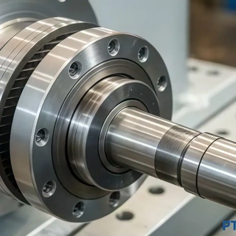
Step turning is a lathe operation used to machine a cylindrical part with two or more different diameters along the same axis. Each change in diameter creates a shoulder, or step, which gives the process its name. It is commonly used for shafts, spacers, and other parts that need multiple functional sections.
In simple terms, step turning removes material from selected areas of a rotating workpiece so that each section reaches a different size. Unlike plain turning, which produces one uniform diameter, step turning creates a stepped profile for assembly, positioning, or load-bearing purposes.
Step turning can be performed on both manual lathes and CNC lathes, but it is especially common in CNC machining because CNC systems can control step length, diameter, and shoulder position more accurately. This makes the process suitable for parts that require repeatability and tighter tolerances.
Step turning is widely used because many real parts need more than one diameter on the same workpiece. For example, a shaft may need separate sections for bearings, gears, or couplings. By machining these features in one setup, step turning can improve concentricity, reduce repositioning, and support more efficient production.
How Does Step Turning Work?
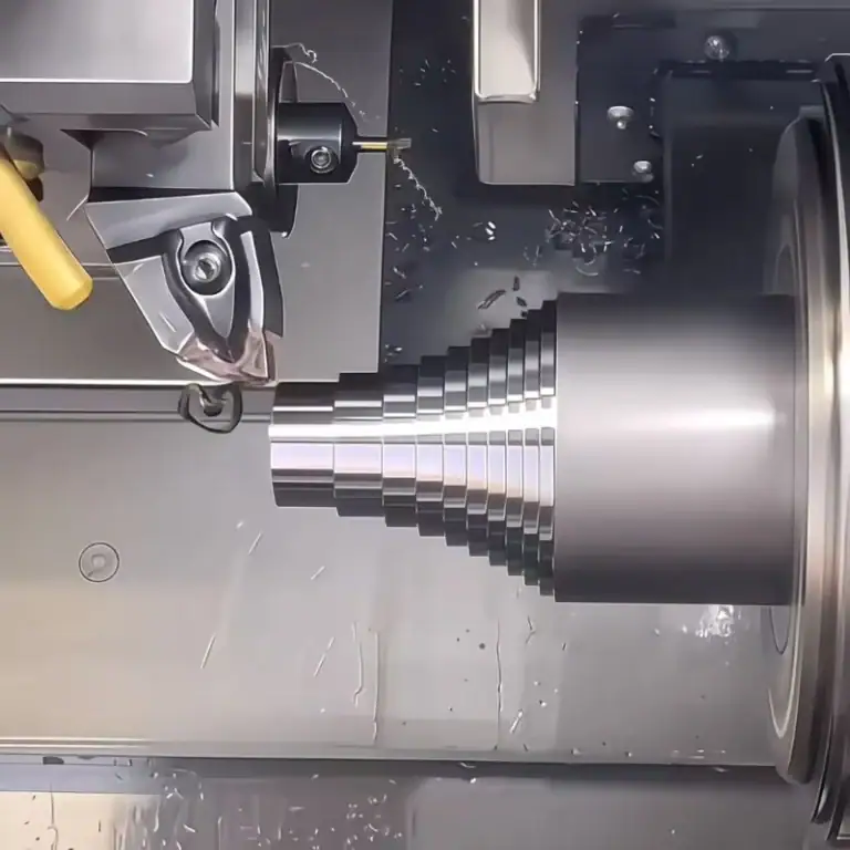
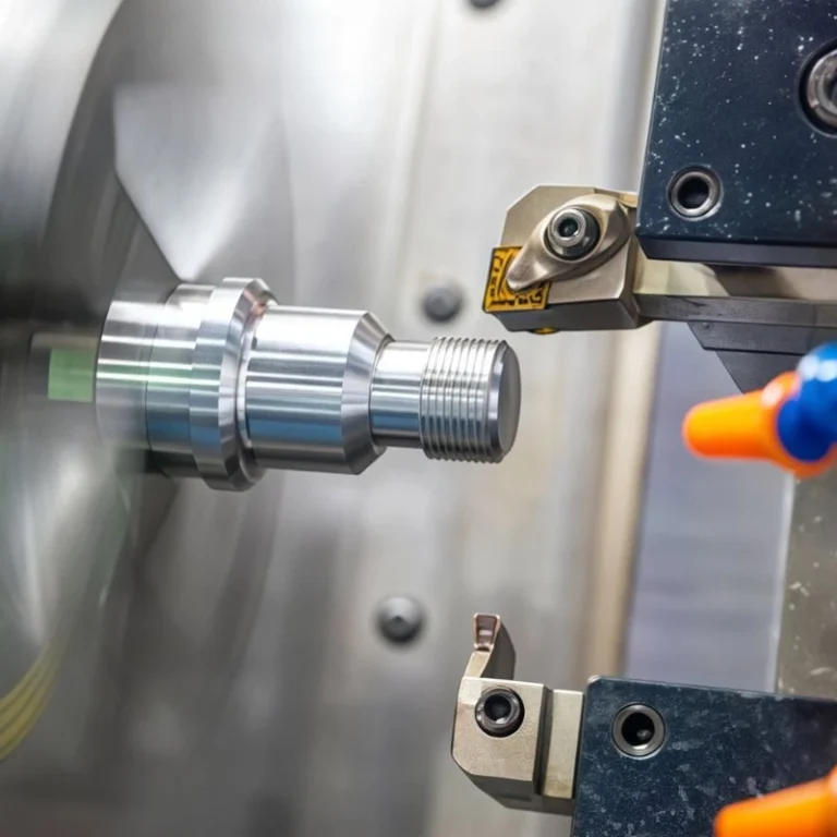
Step turning works by removing material from different sections of a rotating cylindrical workpiece to create multiple diameters along the same axis. Instead of cutting the entire surface to one size, the tool machines selected areas to different depths, forming clear shoulders between each section.
Basic Working Principle
The process begins with the workpiece rotating in the lathe while the cutting tool moves parallel to the axis. By controlling tool position and depth of cut, the operator or CNC system machines one section to a target diameter, then repeats the process at other locations until all required diameter changes are created. This allows several functional sections to be machined while maintaining alignment along the same centerline.
Creating The Stepped Profile
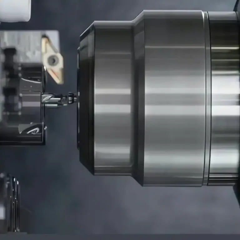
A stepped profile is formed by reducing the diameter of one portion of the workpiece while leaving the adjacent section larger, which creates the shoulder between them. Depending on the part design, the workpiece may include only 2 diameter levels or several different steps, and these stepped areas often serve practical functions such as bearing seats, gear mounting zones, spacers, or locating surfaces.
Rough Turning And Finish Turning
In most cases, step turning is completed in two stages: rough turning removes more material quickly to bring the workpiece close to the required shape, while finish turning refines each diameter, shoulder, and surface finish to meet final specifications. This combination helps balance machining speed with dimensional accuracy, especially when the diameter differences between sections are large.
The Role Of CNC Control
CNC control improves step turning by automatically managing toolpath, shoulder position, step length, and final diameter, which makes the process more repeatable and consistent than manual turning. This is especially valuable in batch production or in parts with tighter tolerances, because once the program is optimized, the same stepped geometry can be produced repeatedly with minimal variation.
What Tools Are Used In Step Turning?
Step turning uses several tools to machine different diameter sections accurately. The main tool is usually a standard turning tool, but other tools may be needed depending on shoulder detail, part geometry, and dimensional requirements.
Standard Turning Tools
Standard turning tools are the most commonly used tools in step turning because they remove material from the outer surface of the workpiece to create the required diameter changes. These tools are used to machine one section at a time, gradually forming the stepped profile along the shaft or cylindrical part.
Grooving And Parting Tools
Grooving and parting tools may also be used in step turning when the part requires narrow shoulders, relief grooves, or sharp transitions between different diameters. These tools help define step boundaries more clearly and are useful when standard turning tools cannot achieve the required detail.
Finishing Tools
Finishing tools are used after rough machining to improve shoulder definition, final diameter accuracy, and surface quality. In many step turning operations, a finishing pass is necessary to meet tighter tolerances and produce a smoother machined surface, especially on functional fit areas.
Measuring Tools
Measuring tools are essential in step turning because each diameter and shoulder position must be checked carefully. Tools such as calipers, micrometers, and depth gauges are commonly used to verify step length, diameter size, and dimensional consistency during or after machining.
CNC Tooling Systems
In CNC step turning, tooling systems are often more advanced and may include indexed inserts, quick-change tool holders, and programmed tool offsets. These systems improve repeatability, reduce setup time, and help maintain consistent results when producing stepped parts in higher volumes.
Tool selection matters because different tools affect material removal, shoulder sharpness, surface finish, and process stability in different ways. Using the right combination of roughing, finishing, and measuring tools helps ensure that the final stepped profile meets both functional and dimensional requirements.
What Are The Main Uses Of Step Turning?
Step turning is mainly used to machine parts that require multiple diameters along the same axis. It is especially common in shaft-like components, where each diameter section serves a different function in assembly, positioning, or motion transfer.
Shafts And Transmission Components
One of the most common uses of step turning is in the production of shafts and transmission parts. Many shafts need different diameter sections to support gears, bearings, pulleys, or couplings, and step turning makes it possible to machine these features accurately on a single workpiece.
Bearing Seats And Mounting Areas
Step turning is also widely used to create bearing seats and mounting surfaces. These areas often require precise diameter control so that bearings, collars, or sleeves can fit correctly, making step turning an important process for parts that rely on accurate assembly.
Spacers, Sleeves, And Bushings
Spacers, sleeves, and bushings often include stepped geometry to fit into larger assemblies or create controlled gaps between components. Step turning is well suited for these parts because it can produce clear shoulders and multiple fit zones in a relatively efficient way.
Mechanical Parts With Functional Diameter Changes
Many mechanical parts need more than one diameter for strength, support, or connection. Step turning is commonly used when a component must combine different functional sections in one design, such as support areas, fitting zones, and threaded or rotating sections.
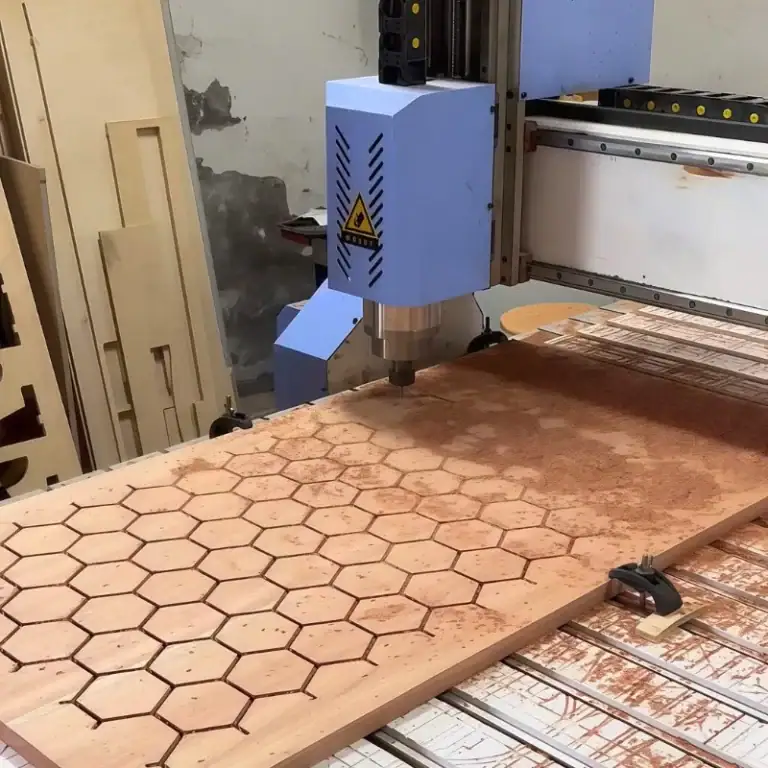
Custom CNC Turned Parts
In CNC turning, step turning is often used for custom parts with non-uniform profiles. It is especially useful when the design requires several diameter changes in one setup, helping manufacturers improve concentricity, reduce repositioning, and produce more consistent parts.
Benefits And Limitations Of Step Turning
Step turning is widely used because it can machine multiple diameters on one workpiece in a controlled and efficient way. At the same time, like any machining process, it also has limitations that should be considered when planning part design and production.
Advantages Of Step Turning
One of the main advantages of step turning is that it allows several diameter sections to be machined in a single setup. This helps reduce repositioning, improve machining efficiency, and shorten overall production time, especially for shaft-like parts with multiple functional zones.
Another important advantage is better alignment and concentricity between stepped sections. Because all features are machined along the same axis, it is easier to maintain dimensional consistency, which is especially valuable for rotating parts and precision assemblies.
Step turning is also highly practical for a wide range of cylindrical parts, including shafts, bearing seats, spacers, sleeves, and custom CNC turned components. In CNC machining, it further improves repeatability, making it suitable for both small-batch and larger production runs.
Limitations Of Step Turning
Despite its advantages, step turning also has some limitations. If the difference between adjacent diameters is large, the process may require significant material removal, which can increase machining time and produce more material waste, especially when starting from solid bar stock.
The process also depends heavily on setup accuracy. If tool position, clamping stability, or machine rigidity is not well controlled, shoulder location and final dimensions may be affected, which can create fitting problems in assembly.
In addition, step turning is mainly suitable for stepped cylindrical profiles. If the part includes more complex contours, tapered features, or non-axisymmetric geometry, other turning methods or secondary machining operations may be needed.
Step Turning Vs. Other Turning Operations
Step turning is only one type of turning operation, and it is often compared with other common methods such as plain turning and taper turning. While all of them are performed on a lathe, each process is used for a different shape and purpose. The main differences are presented in the comparison chart below.
| Turning Operation | Main Purpose | Resulting Shape | Key Feature | Common Applications |
| Step Turning | To machine multiple diameters on the same axis | Stepped cylindrical profile | Produces clear shoulders between diameter changes | Shafts, bearing seats, spacers, sleeves |
| Plain Turning | To reduce the workpiece to one uniform diameter | Straight cylindrical surface | Maintains one constant diameter along the length | Basic shafts, rods, simple cylindrical parts |
| Taper Turning | To create a gradual change in diameter | Conical or tapered surface | Produces a continuous diameter reduction | Tapered shafts, tool holders, conical fittings |
| Contour Turning | To create curved or irregular outer profiles | Non-linear external shape | Produces complex outer geometry | Custom profiles, decorative parts, specialized components |
| Shoulder Turning | To form a single shoulder or transition between diameters | One main step or shoulder | Focuses on one abrupt diameter change | Stops, locating features, simple stepped parts |
What Materials Can Be Used For Step Turning?
Step turning can be applied to a wide range of machinable materials, as long as the workpiece can be rotated and cut accurately on a lathe. The best material choice depends on the part’s function, strength requirements, surface finish expectations, and production cost. In practice, step turning is commonly used for both metals and some engineering plastics.
Aluminum And Brass
Aluminum is also widely used in step turning because it is lightweight, easy to machine, and suitable for high-speed production. It is often chosen for parts that require good dimensional accuracy with lower weight, such as housings, spacers, and lightweight shafts. Brass is another good option because it offers smooth machinability and can produce clean surface finishes, making it suitable for fittings, sleeves, and precision turned parts.
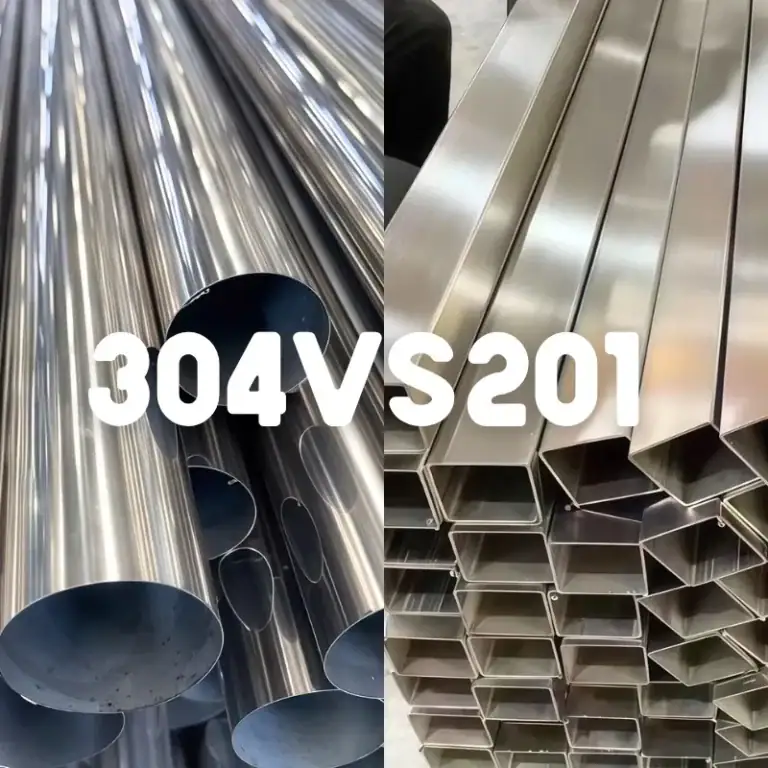
Steel And Stainless Steel
Steel is one of the most common materials used for step turning because it offers good strength, durability, and broad industrial use. Carbon steel is often selected for general shafts, mechanical parts, and structural components, while stainless steel is preferred when corrosion resistance is important. Since stainless steel is tougher to machine than mild steel, cutting parameters and tool selection usually need closer control.
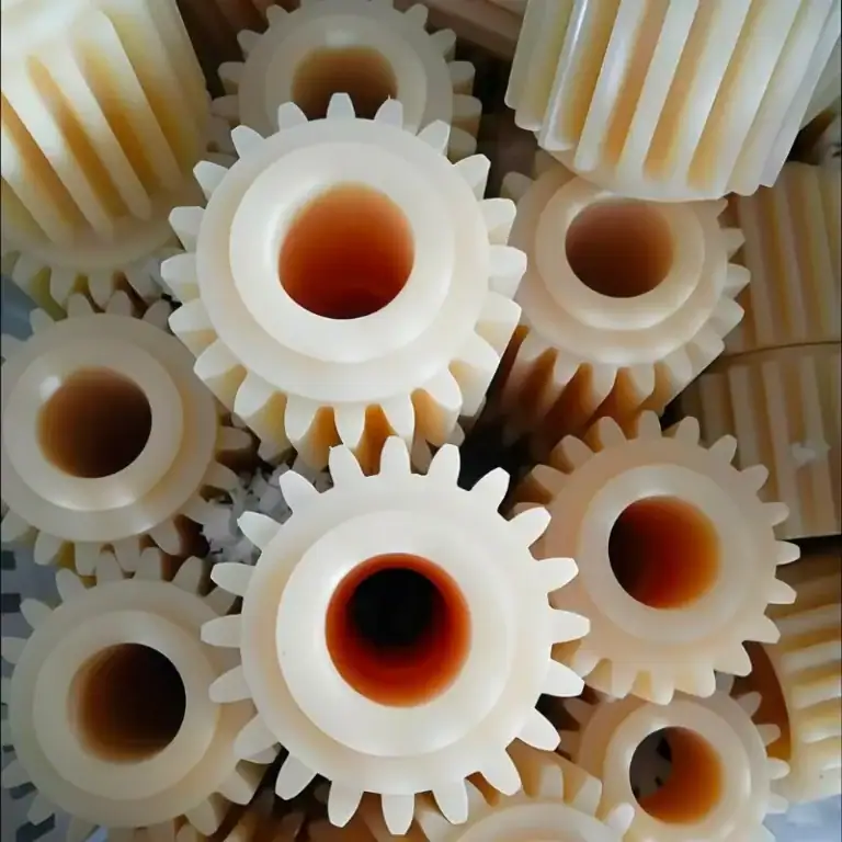
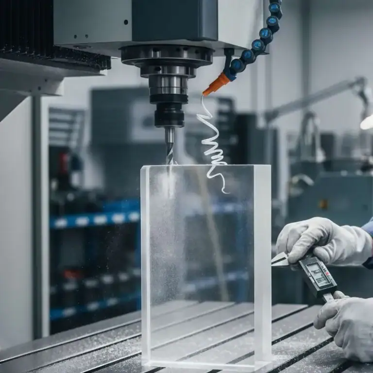
Engineering Plastics And Other Materials
In addition to metals, some engineering plastics can also be used for step turning, especially when the part needs low weight, electrical insulation, or chemical resistance. Materials such as nylon, POM, PTFE, and acrylic may be step-turned depending on the design and application. However, these materials usually require more careful control of heat and cutting forces because they can deform more easily than metals during machining.
Why Material Selection Matters
Choosing the right material for step turning helps ensure that the finished part meets both functional and manufacturing requirements. A suitable material can improve machinability, reduce production time, and support better dimensional accuracy. In many cases, the best results come from balancing part performance, machinability, and cost before production begins.
What Factors Affect Step Turning Quality?
The quality of step turning depends on more than just the machine itself. To produce clean shoulders, accurate diameters, and stable surface finish, several machining factors must work together. If any of these are not properly controlled, the final stepped profile may not meet the required dimensions or functional fit.
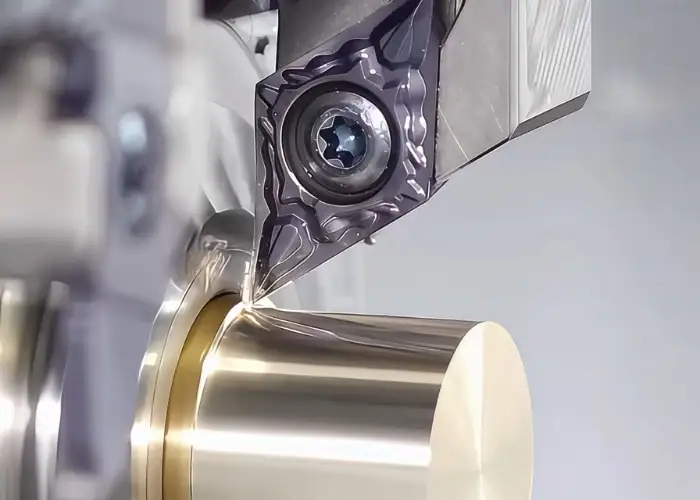
Tool Selection And Tool Geometry
Tool choice has a major effect on step turning quality. The cutting tool must be suitable for the material, the shoulder detail, and the required surface finish. Tool geometry also matters, because rake angle, nose radius, and insert shape can influence cutting forces, chip control, and how clearly the shoulder is formed.
Feed Rate, Cutting Speed, And Depth Of Cut
Cutting parameters directly affect the final result. If feed rate is too high, the surface may become rougher and the shoulder definition may suffer. If cutting speed is too high, excessive heat may increase tool wear. Depth of cut must also match the material and setup, because unstable or overly aggressive cutting conditions can reduce dimensional accuracy and machining stability.
Workpiece Setup And Clamping Stability
A stable setup is essential for good step turning quality. If the workpiece is not clamped securely or if there is too much overhang, vibration and deflection may occur during machining. This can affect shoulder position, diameter size, and overall consistency, especially on longer shafts or smaller-diameter sections.
Machine Rigidity And Alignment
Machine rigidity and alignment also play an important role. A lathe with poor rigidity or misalignment can introduce chatter, dimensional error, or uneven cutting. For precise step turning, the machine, tool holder, and workpiece must all remain properly aligned throughout the operation.
Material Type And Machinability
The material being machined affects how easily the stepped profile can be produced. Harder materials may increase tool wear and cutting force, while softer or more ductile materials may create chip control problems or poorer surface finish. Good machinability usually makes it easier to achieve stable cutting and better dimensional control.
Measurement And Process Control
Step turning quality also depends on inspection and process control. Diameters, shoulder locations, and step lengths should be checked during machining, especially when the part has tighter tolerances. Using the right measuring tools and monitoring cutting performance helps catch errors early and improve repeatability from part to part.
FAQs
What Is Step Turning In Lathe Machine?
Step turning in a lathe machine is a turning operation used to produce a cylindrical part with 2 or more different diameters along the same axis. The change between diameters forms a clear shoulder or step, usually close to 90°. It is commonly used for shafts, spacers, and bearing seats that require multiple functional sections. In CNC and conventional lathes, step turning improves dimensional control and reduces setup changes when machining stepped profiles on a single workpiece.
What Are The Steps In Step Turning?
The basic steps in step turning usually include workpiece setup, marking or programming step locations, selecting the cutting tool, rough turning, finish turning, and dimensional inspection. First, the bar is mounted and aligned in the lathe. Then the diameters and step lengths are defined according to the drawing. Material is removed section by section until the required diameters are achieved. In many cases, tolerance checks are made after each stage, especially when step accuracy must stay within ±0.02 mm to ±0.05 mm.
What Is The Purpose Of Step Turning?
The main purpose of step turning is to machine a part with multiple diameters in a controlled and accurate way. This is important for components such as shafts, where different sections may need to fit bearings, gears, bushings, or couplings. Instead of using separate machining setups, step turning allows these features to be produced in one continuous turning process. This improves dimensional consistency, reduces production time, and helps maintain concentricity between diameter changes along the same axis.
Conclusion
Step turning is a practical and widely used turning process for machining cylindrical parts with multiple diameters along the same axis. It is especially useful for shafts and other components that require clear shoulders, accurate stepped profiles, and reliable dimensional consistency. When used correctly, step turning can help improve machining efficiency, part quality, and overall production stability.
At TiRapid, we support custom CNC turning projects with reliable machining expertise, strict quality control, and flexible production capacity. Whether you need stepped shafts, precision turned parts, or custom cylindrical components, our team can help turn your drawings into accurate, production-ready parts.