Welding defects are a major reason welded joints fail to meet strength, sealing, and appearance requirements. Some defects are visible on the surface, while others remain hidden and require inspection or non-destructive testing to detect. More than cosmetic issues, they can reduce fatigue life, weaken load capacity, increase corrosion risk, and cause leakage. This guide focuses on types of welding defects, including their classification, causes, early detection, and prevention.
What Are Welding Defects?
A welding defect is an imperfection in a welded joint that goes beyond the acceptable tolerance of the process and weakens the weld. It may appear in the weld metal, the base material beside it, or the heat-affected zone around the joint.
Not every irregularity is automatically a rejectable defect. Industry sources distinguish between general discontinuities and true defects, with acceptance depending on the type, size, and location of the flaw and whether it compromises the weld’s intended use.
Welding defects matter because they can reduce strength, appearance, sealing ability, and long-term reliability. In many cases, they are linked to incorrect welding patterns, poor material preparation, unsuitable settings, or unstable process control during welding.
Main Categories of Types of Welding Defects
Most types of welding defects can be grouped into three broad categories: external defects, internal defects, and dimensional or shape-related defects. This kind of classification makes it easier to understand which defects can be seen directly, which require inspection tools, and which mainly affect fit-up or final geometry.
External Welding Defects
External welding defects are usually visible on or near the weld surface. Common examples include cracks, undercut, overlap, spatter, and burn-through. These defects are often identified during visual inspection, but even surface defects can have a serious effect on fatigue performance, corrosion resistance, and final weld appearance.
Internal Welding Defects
Internal welding defects are hidden inside the weld or along the root area. Common examples include porosity, slag inclusions, lack of fusion, and incomplete penetration. Because they are not always visible from the outside, they are often more dangerous in structural or pressure applications and may require ultrasonic, radiographic, or other non-destructive testing methods.
Dimensional and Shape-Related Defects
Some welding defects are mainly related to weld shape, geometry, or dimensional stability. Distortion, underfill, excess reinforcement, and poor bead profile are typical examples. These may not always look as severe as cracks or lack of fusion, but they can still cause fit-up problems, uneven stress distribution, additional machining, or rejection during quality checks.
Why This Classification Matters?
This classification is useful because it helps manufacturers choose the right inspection method and correction strategy. Surface defects may be corrected through better operator technique or parameter control, while internal defects often require stricter joint preparation, shielding, and inspection procedures. Dimensional defects may point to heat input imbalance or poor fixturing.
12 Common Types of Welding Defects
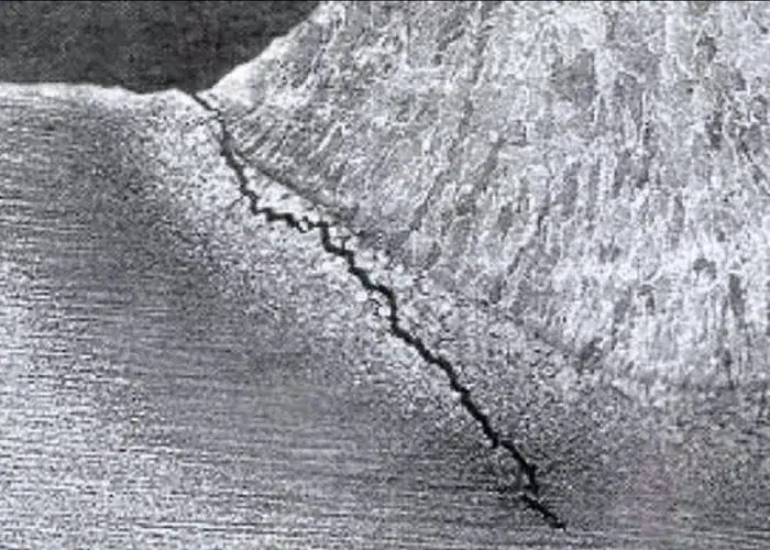
1. Cracks
Cracks are among the most serious welding defects because they can grow under stress and lead to sudden failure. They may appear in the weld metal, the heat-affected zone, or the base material next to the joint.
Common forms include hot cracks, cold cracks, crater cracks, and heat-affected zone cracks. They are often linked to high residual stress, rapid cooling, poor filler selection, excessive hardness, or unsuitable joint design.
Prevention usually depends on better heat control, correct filler metal, proper joint preparation, and, when needed, preheat or controlled cooling. Because cracks directly threaten weld integrity, they are often treated as rejectable defects.
2. Underfill
Underfill occurs when the weld face is left below the surrounding surface or below the required weld profile. In simple terms, the joint is not filled with enough weld metal, so the finished section is thinner than intended.
This condition may result from too little filler deposition, poor travel control, incorrect current, or poor technique that removes more metal than is added. It can also appear after grinding or finishing if too much weld reinforcement is removed.
Underfill can reduce throat thickness and lower the strength of the joint, especially in loaded welds. Prevention requires proper bead size, correct parameter setup, and inspection against the specified weld profile before the part moves forward in production.
3. Undercut
Undercut is a groove melted into the base metal beside the weld toe that is not fully filled by weld metal. It creates a thinner section at the edge of the joint and can become a stress concentration point during service.
It is usually caused by excessive current, fast travel speed, poor torch angle, or incorrect manipulation. Manual processes such as SMAW, GMAW, and FCAW are especially prone to undercut if settings or operator technique are not well controlled.
Prevention focuses on balanced heat input, proper travel speed, and improved weld bead control. Although it is easy to spot visually, undercut should not be ignored because it can reduce fatigue strength in loaded structures.
4. Overlap
Overlap happens when molten weld metal rolls onto the base material without properly fusing to it. The surface may look filled, but the metal sits over the edge instead of forming a sound metallurgical bond with the parent material.
This defect is often caused by low travel speed, poor electrode angle, oversized weld metal deposition, or incorrect manipulation. It tends to appear when the weld pool is allowed to spread beyond the joint edge without enough fusion at the toe.
Prevention usually means improving travel speed, bead placement, and heat balance so the weld fuses correctly instead of piling up. Overlap is a surface defect, but it still weakens the joint because the unfused area can act as a crack starter.
5. Burn-Through
Burn-through occurs when the weld metal and base material melt completely through the joint, leaving a hole or excessively open root. It is most common in thin materials or poorly controlled root areas where the heat input is too high.
Typical causes include excessive current, slow travel speed, large root opening, poor fit-up, or lack of backing support. Once the root area overheats, the molten metal can drop out and create a local opening instead of a sound weld.
Prevention depends on lower heat input, tighter joint control, better backing, and more stable parameter settings. Burn-through is usually easy to see, but in production it can still cause major scrap or rework, especially on thin sheet assemblies.
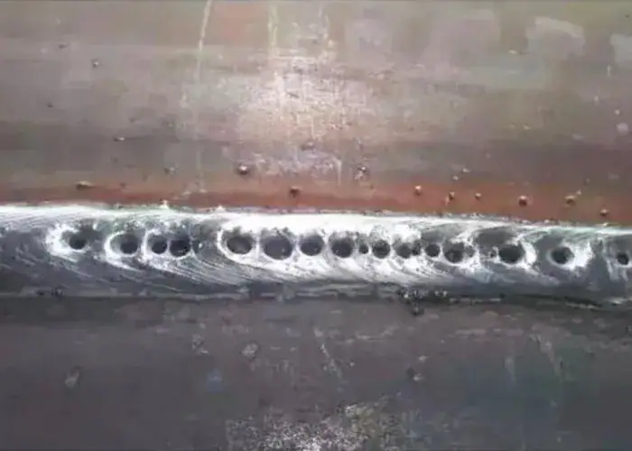
6.Porosity
Porosity refers to gas pockets trapped inside the weld during solidification. It may appear as scattered pores, clustered porosity, or elongated wormhole-like voids, and it can weaken the weld, reduce sealing performance, and affect long-term reliability.
This defect is commonly caused by contamination such as oil, rust, paint, moisture, or mill scale. Inadequate shielding gas, damp consumables, and unstable welding parameters can also allow gas to remain trapped in the molten weld pool instead of escaping during solidification.
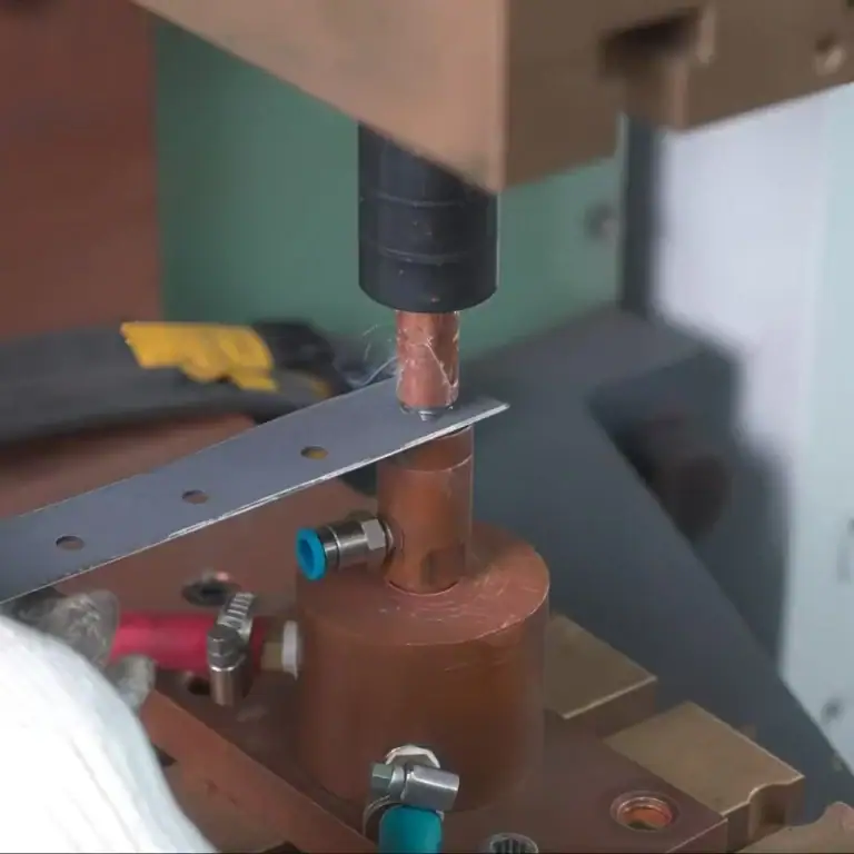
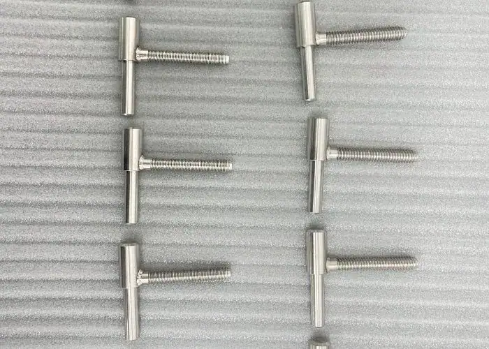
In real manufacturing, porosity can lead not only to strength and appearance problems, but also directly to leakage failure in functional welded assemblies. For example, we once produced a welded SUS304 part for a customer in the semiconductor automation equipment industry, and the part had to pass an airtightness test with no leakage for 30 minutes under 60 Pa pressure. In this kind of application, porosity, lack of fusion, incomplete penetration, or small crack-like defects can all become direct leak paths. That is why sealing-related welded parts must be evaluated not only for weld appearance and strength, but also for airtight performance after welding.
7. Lack of Fusion
Lack of fusion means the weld metal does not properly fuse with the base material or with a previous weld pass. The weld may look acceptable on the surface, but the unfused boundary inside the joint creates a serious reduction in strength.
This defect is usually linked to insufficient heat input, wrong torch angle, poor joint access, contamination, or excessive travel speed. It may occur at the side wall, between passes, or at the root if the arc does not adequately melt both joining surfaces.
Because lack of fusion is often internal, it may need ultrasonic or radiographic inspection to confirm. Prevention depends on correct penetration, clean surfaces, proper joint design, and welding settings that fully melt the required contact faces.
8. Incomplete Penetration
Incomplete penetration, also called lack of penetration, happens when the weld does not extend fully through the joint thickness at the root. The weld bead may appear sound from the outside, but the root remains only partly joined.
It is commonly caused by insufficient heat input, incorrect root opening, poor groove preparation, or excessive travel speed. If the joint geometry or parameter setup prevents the arc from reaching the root, full penetration cannot be achieved.
This defect reduces the effective weld thickness and can lower load capacity in structural and pressure applications. Prevention usually involves better joint design, correct fit-up, and welding settings that achieve proper root fusion from the start.
9. Slag Inclusions
Slag inclusions are nonmetallic particles trapped inside the weld or between weld passes. They are most often associated with processes that produce slag, such as SMAW and FCAW, especially when cleaning between passes is incomplete.
This defect may be caused by poor interpass cleaning, narrow groove angles, inadequate penetration, or incorrect bead placement. If slag is not removed before the next pass or cannot float out of the molten pool, it becomes trapped in the weld.
Slag inclusions reduce weld soundness and may create local stress concentrations. They are often difficult to see from the surface, so radiographic or ultrasonic inspection may be needed. Prevention depends on proper cleaning, access, and bead sequencing.
10. Distortion
Distortion is the unwanted change of shape caused by uneven heating and cooling during welding. Parts may bend, twist, shrink, or pull out of position, making assembly difficult even when the weld itself is otherwise acceptable.
It is often caused by excessive heat input, unbalanced weld sequence, weak fixturing, or asymmetric joint design. Thin materials and long seams are especially sensitive because they respond quickly to thermal expansion and contraction.
Control methods include balanced welding sequence, stronger clamping, tack planning, lower heat input, and better fixture design. Distortion is not always a metallurgical defect, but it can still cause part rejection because geometry and fit-up no longer meet requirements.
11.Spatter
Spatter consists of small droplets of molten metal expelled during welding and stuck to the surrounding surface. It is usually treated as a surface quality problem rather than a deep structural defect, but it can increase cleanup time and finishing cost.
It is commonly associated with MIG, FCAW, and stick welding. Unstable arc conditions, poor voltage and wire feed balance, excessive current, or unsuitable shielding gas can all increase the amount of spatter around the weld zone.
Spatter can be reduced by optimizing parameters, maintaining stable arc length, using correct consumables, and improving technique. Even though it may not always weaken the weld directly, it can lower appearance quality and add downstream labor.
12. Lamellar Tearing or Whiskers
Lamellar tearing is a cracking-related defect that usually appears in rolled steel plates, especially through the thickness direction near restrained joints. It is linked to shrinkage stress and poor through-thickness ductility in the base material rather than simple surface technique alone.
Whiskers are small filament-like metal projections that can appear from root-side penetration in some welds. UTI lists whiskers among common welding defect types because they may indicate uncontrolled penetration or poor root behavior in certain welding situations.
These defects are less common than porosity or undercut, but they still matter in critical fabrication. Prevention depends on suitable base material, lower restraint, better joint design, and tighter root control when penetration behavior must stay within code limits.
What Causes Welding Defects?
Welding defects rarely come from a single cause. In most cases, they result from material condition, welding parameters, joint design, consumable quality, shielding protection, and operator technique working together. When several small issues overlap, the risk of visible and hidden defects rises quickly. Most weld defects are linked to poor preparation, incorrect settings, contamination, consumable problems, or unstable process control.
Poor Joint Preparation
Poor joint preparation is one of the most common root causes of welding defects. If the groove angle, root gap, fit-up, or alignment is incorrect, the weld may not penetrate properly or may trap slag, gas, or unfused areas inside the joint.
Improper preparation often leads to lack of fusion, incomplete penetration, undercut, and even burn-through. Joints that are too tight, too wide, or poorly aligned make it harder for the weld pool to behave predictably, especially in multi-pass or root-sensitive welding work.
Good preparation means using the correct bevel design, maintaining a consistent root opening, aligning parts accurately, and checking accessibility before welding begins. In many shops, better preparation alone can eliminate a large share of recurring weld quality problems.
Incorrect Welding Parameters
Incorrect welding parameters are another major cause of weld defects. If current, voltage, travel speed, arc length, wire feed speed, or heat input are outside the proper range, the weld pool may become unstable and the joint may not form correctly.
Too much heat can cause undercut, burn-through, distortion, and excessive reinforcement. Too little heat can lead to lack of fusion, incomplete penetration, and poor bead shape. Fast travel speed may leave the joint underfilled, while slow travel speed may increase overlap or overheating.
Controlling parameters is not only about setting the machine correctly. It also requires matching the settings to the material thickness, joint geometry, position, and welding process. Stable results usually come from procedure qualification, testing, and disciplined process control rather than guesswork..
Contamination on the Workpiece
Surface contamination is one of the main causes of porosity, poor fusion, and unstable weld quality. Oil, grease, paint, rust, moisture, oxide layers, and dirt can interfere with arc behavior and prevent clean fusion between the weld metal and the base material.
Contamination is especially harmful in processes that rely on clean surfaces and stable gas shielding. Materials such as aluminum and stainless steel are particularly sensitive because oxide layers and surface residue can quickly affect weld soundness and appearance.
Preventing contamination-related defects usually requires proper cleaning before welding, dry storage of materials, and avoiding moisture or oil exposure in the work area. In many cases, a simple cleaning failure can create major downstream repair or rejection costs.
Consumable and Shielding Problems
Welding defects can also come from the wrong filler metal, damp electrodes, poor wire condition, or incorrect shielding gas selection. If the consumables do not match the material or process, weld quality can deteriorate even when the operator follows the correct procedure.
Moisture in electrodes or flux can increase hydrogen-related cracking risk. Poor shielding gas flow or disturbed gas coverage can cause porosity and oxidation. Incorrect filler composition may reduce strength, increase crack sensitivity, or create unacceptable metallurgical behavior in the weld zone.
To prevent these problems, manufacturers usually control consumable storage, verify gas flow before welding, and select filler metals according to qualified procedures. Consumable management is often treated as a quality control issue, not just a material handling issue.
Operator and Procedure Issues
Even when materials, equipment, and consumables are correct, welding defects can still be caused by poor technique or inconsistent procedure use. Torch angle, arc length, weaving pattern, interpass cleaning, and weld sequence all affect final weld quality.
Operator-related errors often lead to spatter, undercut, overlap, slag inclusions, and irregular bead shape. In repetitive production, inconsistent execution between operators may also create unstable quality results, even when the same machine and materials are used.
This is why qualified welding procedures and welder training are so important. A controlled process does not depend only on equipment capability. It also depends on whether the weld is performed the same way, under the same rules, every time.
How to Prevent Welding Defects?
Preventing welding defects is usually more effective and less costly than repairing them later. In most manufacturing environments, prevention starts before welding begins, with proper preparation, stable parameters, clean materials, and a controlled workflow. It also requires good fit-up, suitable consumables, reliable shielding, and consistent welder technique.
Use the Correct Welding Parameters
Incorrect current, voltage, travel speed, wire feed speed, or heat input can quickly create defects such as undercut, burn-through, incomplete penetration, overlap, or poor bead shape. Stable welding quality depends heavily on using parameters that match the joint and material.
Too much heat can distort the part or overmelt the joint, while too little heat can leave the weld incompletely fused. Speed also matters: if travel is too fast, filling and penetration may be insufficient, if it is too slow, overheating and excess buildup may occur.
The best way to avoid parameter-related defects is to use qualified welding procedures, tested settings, and consistent machine control. Parameter selection should always match material thickness, joint design, welding position, and process type.
Select Suitable Filler Materials and Shielding Gas
Weld quality depends not only on the machine, but also on using the correct consumables. A mismatched filler metal can reduce strength, increase crack sensitivity, or create unsuitable metallurgical behavior, while poor shielding conditions can lead to porosity and oxidation.
Moisture in electrodes, flux, or filler material can increase the risk of hydrogen-related cracking. At the same time, poor gas flow, gas leaks, or disturbed shielding coverage can prevent proper weld protection and allow contamination to affect the molten metal.
Prevention usually means storing consumables correctly, checking gas flow before welding, and selecting filler and shielding combinations according to the approved procedure. In many factories, this is treated as part of quality control, not just material handling.
Improve Fit-Up and Joint Preparation
Good fit-up and joint preparation are critical for preventing incomplete penetration, slag inclusions, lack of fusion, and burn-through. If the root opening, groove angle, alignment, or access is wrong, the weld will be harder to control and much more likely to develop defects.
This is especially important in multi-pass welding, root-pass welding, and thicker joints where weld geometry strongly affects penetration and slag removal. Even a skilled welder may struggle to produce a sound weld if the joint itself is poorly prepared.
Better fit-up means more than just bringing two parts together. It means using the right bevel design, correct gap, proper alignment, and enough access for the selected welding method to perform consistently.
Control Heat Input and Travel Speed
Heat input and travel speed have a direct effect on penetration, bead shape, distortion, and crack sensitivity. If heat input is too high, the part may distort or burn through. If it is too low, the weld may not fuse or penetrate properly.
Travel speed must also stay within the correct range. A weld made too quickly may show underfill, poor penetration, or irregular fusion. A weld made too slowly may create overlap, excessive reinforcement, or unnecessary heat buildup in the surrounding material.
Manufacturers usually control these risks through procedure qualification, welder training, and process monitoring. Consistent heat input is one of the most important factors in keeping weld geometry and internal quality stable across repeated production runs.
Clean the Joint Properly
Clean joint surfaces are essential for preventing porosity, lack of fusion, and unstable arc behavior. Oil, rust, paint, mill scale, moisture, and oxide layers can all interfere with fusion and trap gas in the weld pool, especially in gas-shielded welding processes.
Proper cleaning methods depend on the material and process, but they usually include degreasing, wire brushing, grinding, or chemical cleaning where needed. Aluminum and stainless steel often require extra attention because surface contamination and oxide films can quickly affect weld quality.
Good cleaning should happen before welding starts, not after a problem appears. In many cases, a well-cleaned joint is one of the simplest and most effective ways to prevent recurring weld defects in production.
Follow Qualified Welding Procedures
One of the most reliable ways to prevent welding defects is to follow a qualified and repeatable welding procedure. Welding quality becomes more stable when operators use approved settings, defined sequences, correct interpass cleaning, and process-specific handling rules.
Procedure control reduces variation between operators, machines, and production batches. It also helps ensure that the same joint is welded under the same conditions every time, which is critical for avoiding unpredictable defects in repetitive manufacturing.
Training matters just as much as documentation. Even the best welding procedure will not prevent defects if it is not followed consistently on the shop floor. Strong prevention depends on both qualified procedures and disciplined execution.
Once a weld defect appears, repair often adds cost, delays production, and may introduce further heat cycles or local weakening. That is why most quality-focused manufacturers try to prevent weld defects at the source instead of relying on repeated rework after inspection.
How to Detect Welding Defects?
Detecting welding defects is essential because many flaws cannot be identified by appearance alone. Surface defects may be visible, but internal problems such as lack of fusion, slag inclusions, and incomplete penetration often need more than a simple visual check. In practice, weld inspection starts with visual examination and then moves to non-destructive testing when deeper verification is required.
Visual Inspection
Visual inspection is the most common weld quality check and the first step in defect detection. It is used to examine the weld surface for visible discontinuities such as cracks, undercut, overlap, burn-through, spatter, poor bead shape, and other surface irregularities.
A good visual inspection does not begin only after welding is finished. ESAB notes that effective visual inspection starts before welding, including checks on cleanliness, bevel condition, fit-up, spacing, tack welds, and in-process weld distribution.
The main limitation of visual inspection is that it cannot reliably detect internal defects. Even if the weld surface looks acceptable, defects such as lack of fusion, incomplete penetration, or internal porosity may still be present and require further testing.
Ultrasonic Testing
Ultrasonic testing uses high-frequency sound waves to examine the internal structure of a weld. It is widely used in non-destructive testing because it can help detect internal discontinuities without cutting or destroying the welded part.
UT is especially useful for finding internal defects such as cracks, lack of fusion, slag inclusions, and incomplete penetration. It is often preferred in structural or pressure-related work where internal soundness matters and direct visual confirmation is not possible.
Its effectiveness depends on proper technique, suitable equipment, and experienced interpretation. In real manufacturing, ultrasonic testing is commonly chosen when weld integrity must be verified without damaging the component.
Radiographic Testing
Radiographic testing uses X-rays or gamma rays to create an image of the weld’s internal structure. This method allows inspectors to evaluate hidden discontinuities by passing radiation through the weld onto film or another imaging medium.
RT is commonly used to identify internal defects such as porosity, cracks, incomplete penetration, and slag inclusions. Because it creates a recordable image, it is especially useful when internal weld condition must be documented and reviewed.
Compared with visual inspection, radiographic testing provides much better visibility into the weld interior. However, it requires specialized equipment, controlled procedures, and qualified interpretation, so it is generally used when defect risk or code requirements justify the added cost.
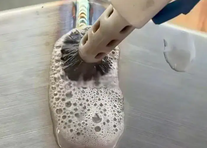
Dye Penetrant Testing
Dye penetrant testing is used to reveal surface-breaking defects by applying a penetrant liquid to the weld surface. The liquid enters small openings, and after excess penetrant is removed, a developer helps make those openings visible to the inspector.
This method is useful for detecting fine surface cracks and other open surface discontinuities that may be difficult to see with the naked eye alone. It is often used as a supplement to visual inspection when surface defect sensitivity needs to be improved.
Its limitation is that it only works on defects that open to the surface. It cannot reveal internal flaws hidden beneath a sound-looking outer layer, so it is often paired with other inspection methods when broader defect detection is needed.
Magnetic Particle Testing
Magnetic particle testing is another surface and near-surface inspection method used on ferromagnetic materials. During the test, the weld area is magnetized, and magnetic particles gather where there is a discontinuity near the surface.
MT is effective for detecting cracks and similar flaws that are open to the surface or just below it. In welding inspection, it is often chosen when steel welds require fast detection of surface-breaking or shallow subsurface discontinuities.
Like penetrant testing, magnetic particle testing is not intended for deep internal flaws. Its value lies in finding crack-related defects quickly on suitable magnetic materials, especially where visual inspection alone may miss small indications.
Different types of welding defects require different inspection methods. Visual inspection is strong for surface flaws such as undercut, overlap, spatter, and burn-through, while UT and RT are more appropriate for internal defects like porosity, slag inclusions, lack of fusion, and incomplete penetration.
Choosing the wrong inspection method can allow serious defects to go undetected. A weld may pass visual inspection but still fail in service if internal flaws were never checked in a critical application. That is why inspection planning must match the defect risk and the function of the welded part.
FAQs
When should a welding defect be considered rejectable?
A welding defect should be considered rejectable when it exceeds the allowed tolerance and affects weld strength, sealing performance, fatigue resistance, or the intended service function of the part. In actual production, acceptance depends on the defect type, size, location, and the quality standard applied to the welded component.
Which welding defects usually require NDT instead of visual inspection alone?
Welding defects hidden inside the weld usually require non-destructive testing instead of visual inspection alone. Common examples include lack of fusion, incomplete penetration, slag inclusions, internal porosity, and some internal cracks, because these flaws may remain undetected even when the weld surface appears normal.
Can all welding defects be repaired, or do some joints need to be remade?
Not all welding defects should be repaired in the same way. Minor surface issues may be corrected, but serious defects such as major cracks, deep lack of fusion, or repeated internal flaws can make repair risky or uneconomical. In critical applications, rejection and remanufacture may be the safer and more reliable option.
Why can the same welding defect keep happening even after repair?
The same welding defect often returns when the root cause has not been removed. If poor joint preparation, unstable parameters, contamination, incorrect consumables, or inconsistent welding technique remain unchanged, repair only fixes the visible result, not the source of the problem. That is why root cause control is more important than repair alone.
Conclusion
Welding defects can reduce joint strength, appearance, sealing performance, and long-term reliability in welded parts. Understanding the main types of welding defects, along with their causes, prevention methods, and detection techniques, helps manufacturers improve weld quality and reduce production risk.
At TiRapid, we provide precision CNC machining and manufacturing services for custom metal parts, welded assemblies, and industrial components for industries such as automotive, robotics, and industrial equipment.