Holes are among the most fundamental features in mechanical design, yet the types of holes used in engineering and machining are far more diverse than they first appear. From simple through holes to precision reamed bores and deep drilled passages, each hole type serves a specific structural or functional role. The correct selection of hole geometry, diameter, and depth directly affects assembly accuracy, load distribution, sealing performance, and long-term reliability.
This guide explains 16 types of holes commonly used in engineering, how they are classified, how they are machined, and how to select the appropriate hole type based on function, tolerance, and manufacturing constraints.
What Is a Hole Feature in Engineering?
In engineering and machining, a hole feature is an intentionally created opening inside a material designed to perform a specific function in a mechanical part or assembly. It is one of the most common geometric features in mechanical design and is typically used for fastening, positioning, alignment, fluid passage, or weight reduction.
Unlike complex cavities or pockets, a hole is usually defined by clear dimensional parameters that control how it is manufactured and how it interacts with other components. These parameters commonly include:
-
A specified diameter
-
A controlled depth
-
A tolerance requirement
-
A surface finish specification (when applicable)
Hole features are fundamental in mechanical design and are widely used for fastening, alignment, fluid passage, weight reduction, and precision positioning.
From simple drilled through-holes to high-precision bored or reamed holes, the geometry and tolerance class directly influence assembly performance, load distribution, and manufacturing cost.
Understanding hole features is essential for engineers aiming to balance design intent, machinability, and production efficiency.
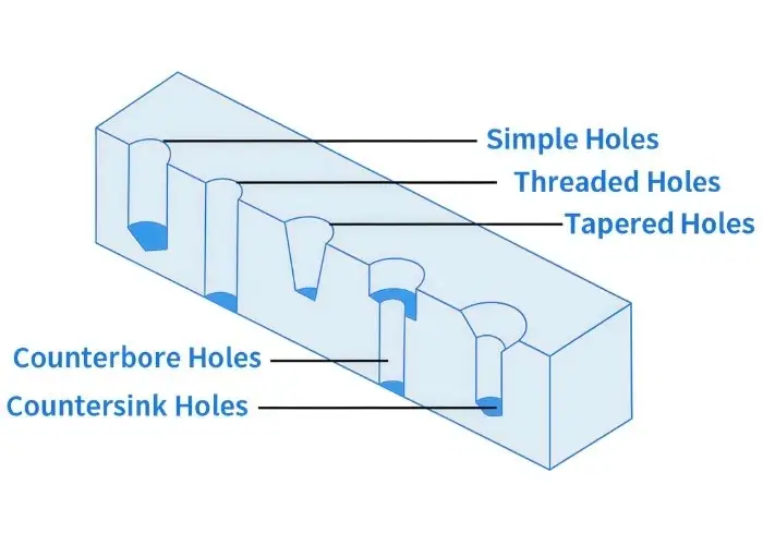
16 Common Types of Holes in Engineering and Machining
Holes in engineering are classified based on geometry, depth, and functional purpose. Each hole type serves a specific role in fastening, alignment, fluid transfer, or structural positioning.In CNC machining, selecting the correct hole type directly impacts tolerance control, assembly reliability, and overall manufacturability.
1.Simple Hole
A simple hole is the most fundamental internal feature in mechanical and structural components, maintaining a constant diameter along its entire depth. It is typically produced using standard drilling operations and requires minimal machining complexity.
Simple holes are widely used for fastening points, alignment references, ventilation paths, and weight reduction in machined parts. Because of their straightforward geometry, they are easy to inspect, manufacture, and integrate into high-volume CNC machining processes.
In many engineering designs, simple holes serve as the base feature before additional operations such as threading, reaming, or counterboring are applied. They are commonly found in structural brackets, machine housings, and mounting plates where straightforward drilling is sufficient to meet functional requirements.
2.Through Hole
A through hole extends completely through the thickness of a component, allowing fasteners, shafts, cables, or fluids to pass from one side of the material to the other. This hole type is widely used in bolted joints, structural connections, and fluid transport systems.
From a machining perspective, through holes are easier to produce than blind holes because chips can evacuate freely during drilling or boring operations. This improves tool life, reduces heat buildup, and helps maintain stable cutting conditions.
Through holes are also easier to inspect and measure because both ends of the hole are accessible. In CNC machining, they are frequently used for bolt patterns, mechanical linkages, pipe connections, and electrical routing channels.
3.Blind Hole
A blind hole has a defined depth and terminates inside the material rather than passing through the entire component. This type of hole is commonly used when the opposite side of the part must remain sealed or when space constraints prevent a through-hole design.
Blind holes are often used for threaded fasteners, concealed mounting features, and compact mechanical assemblies. Because the hole stops inside the material, machining requires accurate depth control and proper chip evacuation.
If chips accumulate at the bottom of the hole, heat buildup may occur, increasing tool wear and reducing dimensional accuracy. For this reason, blind hole drilling typically requires optimized feed rates, proper coolant flow, and sometimes peck drilling cycles in CNC machining.
4.Tapered Hole
A tapered hole gradually changes in diameter along its axis, creating a conical internal surface rather than a straight cylindrical bore. This geometry allows tapered components such as pins or shafts to seat firmly while maintaining precise alignment.
Tapered holes are frequently used in machine tool assemblies, alignment systems, and precision mechanical joints where controlled positioning is critical. Because the taper provides self-centering capability, it helps ensure repeatable assembly and accurate positioning of mating components.
These holes are typically produced using tapered reamers, specialized drills, or precision machining operations designed to maintain a consistent taper angle.
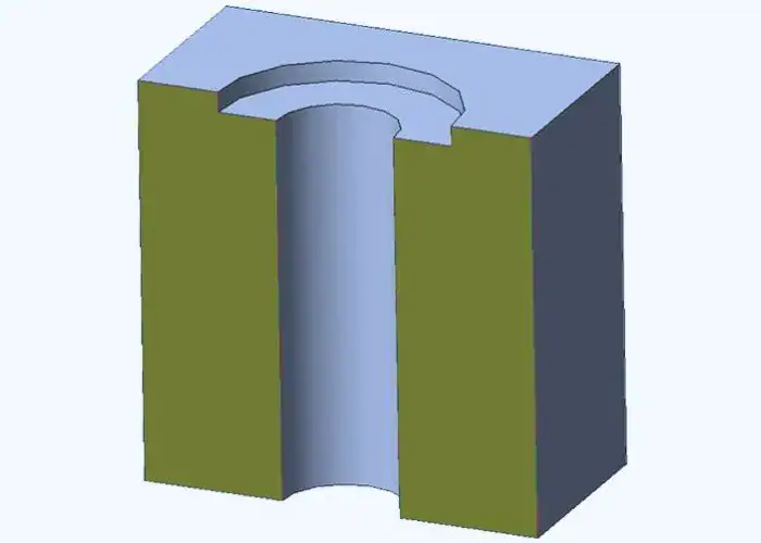
5.Counterbore Hole
A counterbore hole consists of a cylindrical hole combined with a larger flat-bottom recess at the opening. This stepped design allows bolt heads, particularly socket head cap screws, to sit flush with or below the part surface.
Counterbored holes are commonly used in mechanical assemblies where protruding fasteners would interfere with moving components or where a smooth external surface is required. Examples include machine frames, equipment housings, and structural mounting plates.
Maintaining concentric alignment between the counterbore and the main hole is essential to ensure that the fastener seats correctly and distributes load evenly.
6.Countersink Hole
A countersink hole features a conical recess at the hole entrance designed to accommodate flat-head screws. When installed, the screw head sits flush with the surrounding surface.
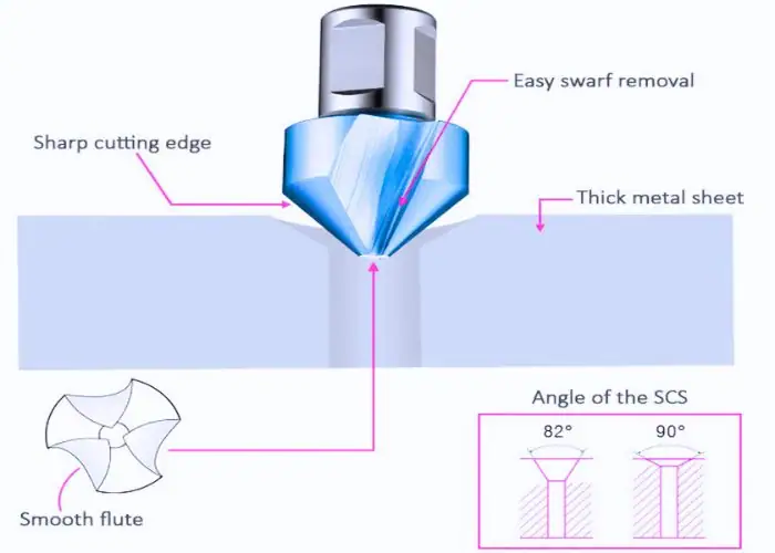
Countersinks are widely used in sheet metal assemblies, aerospace panels, and structural components where aerodynamic smoothness or aesthetic appearance is important. The most common countersink angles are 82°, 90°, and 100°, depending on the fastener standard.
Accurate angle matching between the countersink and the fastener head is critical to ensure proper load transfer and avoid localized stress concentration around the hole.
7.Spotface Hole
A spotface hole is a shallow machining feature created around the opening of a drilled hole to produce a flat seating surface. This ensures that bolts, nuts, or washers sit evenly against the part surface.
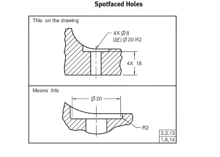
Spotfacing is especially useful when the base material surface is rough, cast, or uneven. Without spotfacing, the fastener may not contact the surface evenly, which could lead to uneven load distribution or loosening during operation.
Spotface features are commonly used in castings, forged parts, and structural assemblies where surface irregularities are common.
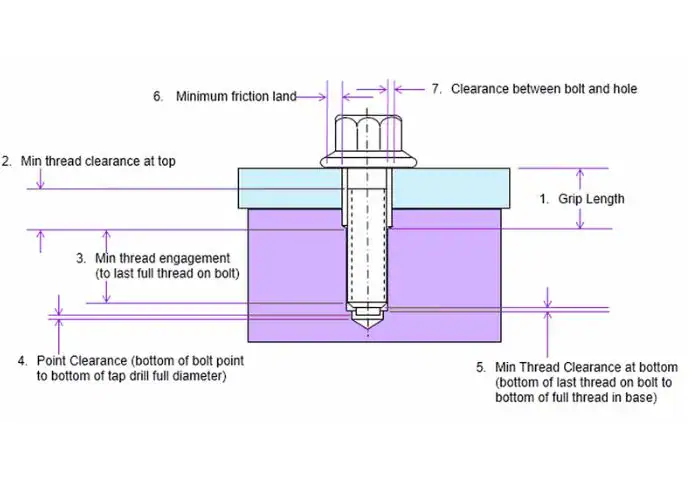
8.Threaded Hole
A threaded hole contains internal threads that allow screws or bolts to engage directly with the component. This eliminates the need for separate nuts and helps create compact mechanical assemblies.
Threaded holes are widely used in machinery, automotive components, and industrial equipment where secure fastening is required. Maintaining proper thread geometry, pitch accuracy, and depth is essential to ensure reliable load transfer.
Poor thread quality can lead to stripped threads, reduced clamping force, or vibration-related loosening in mechanical joints.
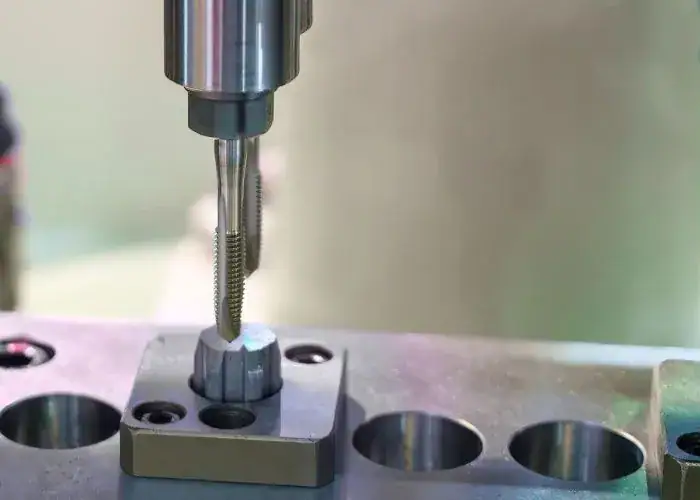
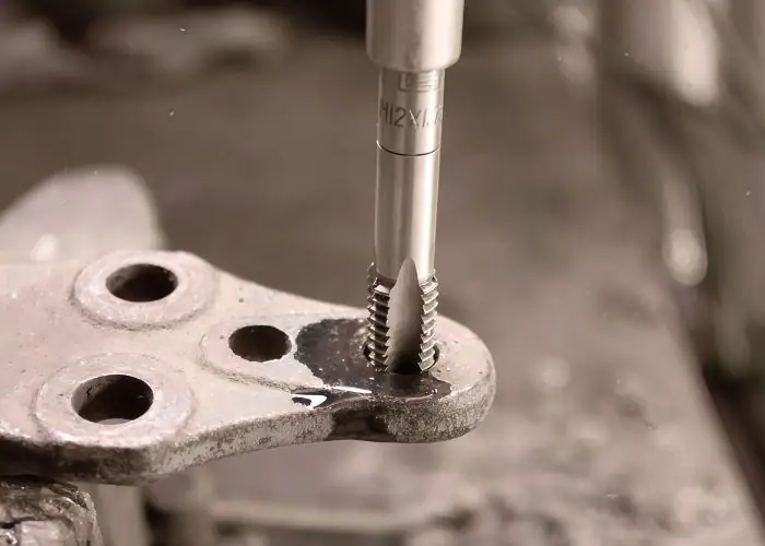
9.Tapped Hole
A tapped hole is produced by drilling a pilot hole and then cutting internal threads using a tapping tool. The term specifically refers to the machining process used to create the threaded feature.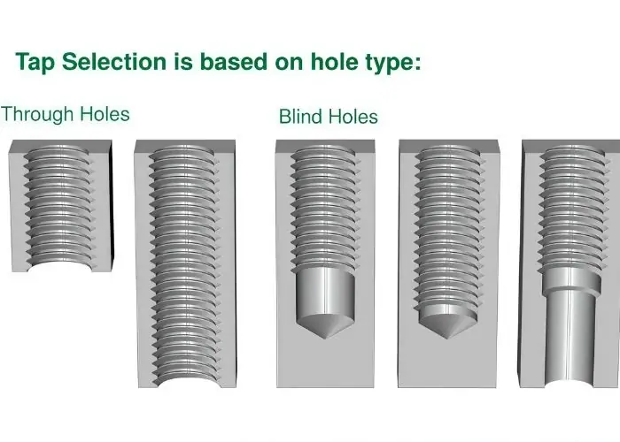
In modern CNC machining environments, tapping operations are often automated to maintain consistent thread quality across large production runs. Correct cutting speed, lubrication, and alignment are critical to prevent tap breakage and maintain thread integrity.
Tapped holes are commonly used in machine housings, mounting brackets, and equipment frames.
10.Screw Clearance Hole
A screw clearance hole is intentionally larger than the fastener diameter so that the screw can pass through freely without engaging threads. The clamping force is instead created in another threaded component or nut.
Clearance holes are typically categorized as close fit, normal fit, or loose fit depending on assembly requirements. Proper clearance sizing ensures smooth installation of fasteners while maintaining accurate alignment between assembled components.
This hole type is commonly used in structural joints, bolted assemblies, and adjustable mounting systems.
11.Counterdrilled Hole
A counterdrilled hole contains stepped internal geometry with two or more diameters along the same axis. It is usually produced by performing multiple drilling operations that enlarge different sections of the hole.
This design allows multiple functions to be integrated into a single feature, such as bolt seating, shaft clearance, or fastener alignment. Counterdrilled holes are commonly used in machine housings, mechanical frames, and structural assemblies.
In CNC machining, counterdrilled holes require accurate alignment between each diameter step. Sequential drilling operations or stepped drill tools are typically used to maintain concentricity and dimensional accuracy.
12.Interrupted Hole
An interrupted hole occurs when the bore intersects another feature such as a slot, cross hole, or open surface. This creates a discontinuous cutting path during machining.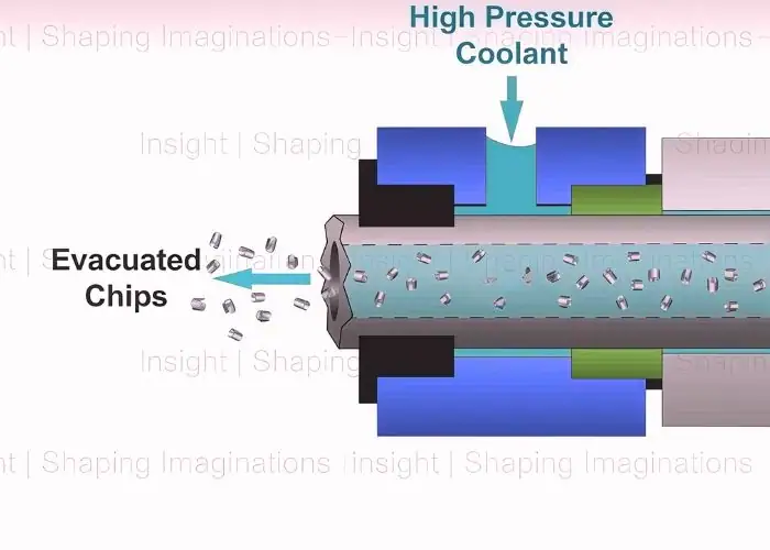
Interrupted holes often appear in parts with intersecting channels, structural cutouts, or complex internal geometries. They are commonly found in hydraulic components, manifolds, and lightweight structural designs.
Because the cutting tool repeatedly loses and regains contact with the material, interrupted holes may cause vibration and tool chatter. Stable fixturing and optimized cutting parameters are required to maintain machining stability
13.Overlapping Hole
Overlapping holes are formed when two adjacent holes partially intersect and share a portion of their internal geometry. This configuration can create combined internal channels or reduce material weight.
They are sometimes used in fluid routing systems, lightweight structures, or components that require intersecting internal passages. The overlapping area allows fluid or airflow to pass between holes.
However, overlapping holes may create stress concentration areas in the surrounding material. Engineers must carefully evaluate load distribution and structural strength to ensure mechanical reliability.
14.Reamed Hole
A reamed hole is a precision-finished cylindrical bore produced by enlarging a previously drilled hole using a reamer. The reaming process improves dimensional accuracy, roundness, and surface finish.
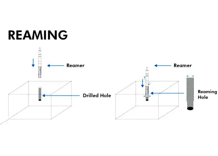
Reamed holes are commonly used for dowel pins, precision shafts, and alignment features in mechanical assemblies where accurate positioning is critical.
Because reaming removes only a small amount of material, the pilot hole must be accurately drilled beforehand. Proper cutting conditions and lubrication help achieve consistent tolerance and surface quality.
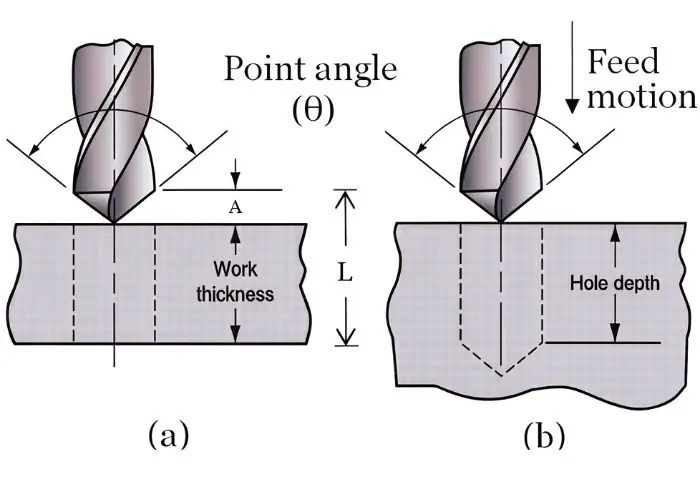
15.Deep Hole
A deep hole is typically defined as a hole with a depth-to-diameter ratio greater than 10:1. As the hole depth increases, machining becomes more difficult due to chip evacuation and tool deflection.
Deep holes are widely used in hydraulic cylinders, aerospace components, and mechanical shafts where long internal passages are required.
Machining deep holes usually requires specialized techniques such as gun drilling or BTA drilling. High-pressure coolant and precise tool guidance help maintain straightness and dimensional accuracy.
16.Slot or Trench Hole
A slot, sometimes called a trench hole, is an elongated opening rather than a circular bore. This geometry allows components to slide or adjust position during assembly.
Engineering Considerations for Hole Design and Machining
Hole design directly affects part performance, assembly accuracy, and machining efficiency. Although holes are simple features, factors such as load distribution, alignment accuracy, material properties, and machining accessibility must be considered. Proper hole design helps ensure structural reliability while keeping CNC machining processes efficient and cost-effective.
Load Distribution
Adding a hole removes material from a component and changes how forces move through the structure. If the hole is too close to an edge or the surrounding wall thickness is insufficient, stress concentration may occur. Engineers usually maintain proper edge distance and material thickness around holes to ensure loads are distributed safely across the part.
Alignment Requirements
Many holes are used to position parts accurately during assembly, especially when combined with dowel pins, shafts, or precision fasteners. Even small positional deviations can cause misalignment between components. Maintaining proper hole location and tolerance control helps ensure smooth assembly and reliable mechanical performance.
Material and Machining Behavior
Different materials behave differently during drilling and machining. Hard materials such as stainless steel require slower cutting speeds and stronger tools, while softer materials like aluminum are easier to machine. Understanding material characteristics helps engineers select proper tools, cutting parameters, and cooling strategies.
Tool Accessibility
Hole location must allow cutting tools to reach the machining area safely and efficiently. Holes placed inside deep cavities or near complex geometries may be difficult to access with standard tools. Designing holes with adequate clearance for tooling helps maintain machining stability and improve production efficiency.
Chip Evacuation and Cooling
During drilling, chips must be removed from the cutting zone to prevent heat buildup and tool damage. Poor chip evacuation can reduce hole quality and surface finish. This issue is especially important for blind holes and deep holes, where chips have limited space to escape.
Manufacturing Efficiency
Hole design should balance performance requirements with manufacturing cost. Extremely tight tolerances or complex hole features increase machining time and inspection effort. Choosing appropriate tolerances and machining methods helps maintain product quality while keeping production efficient.
Tolerances, Fits, and Hole Callouts
Hole performance is closely tied to tolerance classification and fit selection. The way a hole is dimensioned and specified on engineering drawings directly affects assembly behavior, load transfer, and long-term durability. Proper understanding of fits, positional tolerances, and surface finish requirements ensures components function as intended without excessive stress or misalignment.
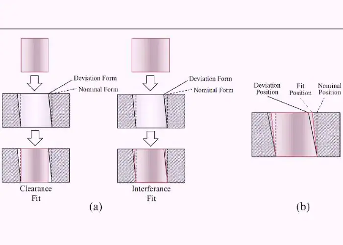
1.Clearance Fit
A clearance fit occurs when the hole diameter is intentionally larger than the shaft diameter, leaving a small gap between the two parts. This gap allows the shaft to move or rotate freely inside the hole without friction or force during assembly. Clearance fits are commonly used in parts that require easy installation, disassembly, or smooth motion.
Typical applications include rotating shafts, sliding components, bearings, and removable fasteners. Because assembly does not require pressing force, clearance fits are widely used in maintenance-friendly designs. Engineers select specific tolerance combinations to ensure reliable movement while still maintaining proper alignment and operational stability.
2.Transition Fit
A transition fit is a compromise between clearance fit and interference fit. Depending on the exact tolerances of the shaft and hole, the assembly may result in either a small clearance or a light interference. This allows parts to be assembled with slight resistance while still maintaining accurate positioning.
Transition fits are commonly used when components must remain well aligned but still allow relatively easy assembly. Typical applications include locating pins, precision couplings, gears, and machine tool components. Because the fit can vary slightly between clearance and interference, engineers carefully select tolerances to balance assembly convenience with improved positional accuracy.
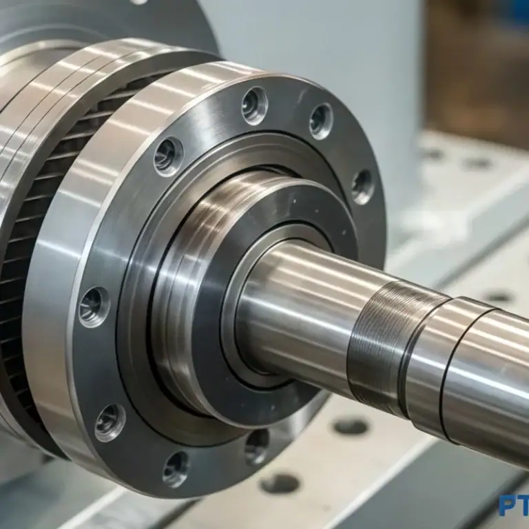
3.Interference Fit
An interference fit occurs when the shaft diameter is intentionally slightly larger than the hole diameter. During assembly, force or thermal expansion methods are required to press the shaft into the hole. Once assembled, the friction between the two surfaces creates a strong mechanical bond.
This type of fit provides excellent load transfer and prevents relative movement between components. Interference fits are widely used in applications such as gears mounted on shafts, bearings in housings, and structural machine parts. Because the parts are tightly joined, this method eliminates the need for additional fasteners while ensuring reliable strength and stability.
4.GD&T Position Tolerance
Position tolerance in Geometric Dimensioning and Tolerancing (GD&T) controls the exact location of a hole relative to other features on a part. Instead of only specifying size, GD&T defines a tolerance zone within which the center of the hole must lie.
This ensures that holes align correctly during assembly, especially when multiple parts must fit together with bolts, pins, or shafts. Position tolerance is commonly used in precision mechanical components, aerospace parts, and automotive assemblies. By clearly defining allowable variation, GD&T helps manufacturers maintain consistent alignment, improve assembly reliability, and reduce production errors.
5.ISO Tolerance System
The ISO tolerance system defines standardized limits for dimensional variation in manufacturing. Hole tolerances such as H7 specify how much the actual hole size can vary from the nominal dimension while still remaining acceptable.
Using standardized tolerances ensures that parts produced by different manufacturers will still fit together correctly. Engineers often combine hole tolerances like H7 with shaft tolerances such as g6 or h6 to create specific fit types. This system provides predictable assembly behavior and simplifies communication between designers, machinists, and quality inspectors.
6.Surface Finish Considerations
Surface finish refers to the microscopic texture of a machined surface, typically expressed as surface roughness values such as Ra. The quality of the surface finish inside a hole can significantly influence component performance.
Smooth surfaces reduce friction and wear, which is important for rotating shafts and bearings. In sealing applications, proper surface finish helps prevent fluid leakage and improves sealing reliability. Surface roughness can also affect fatigue strength under repeated loading. For these reasons, engineers often specify surface finish requirements when designing precision holes used in high-load or high-performance assemblies.
How to Measure Holes Accurately?
Accurate hole measurement is essential to ensure compliance with tolerance requirements and proper assembly performance. Even a small deviation in diameter, roundness, or position can affect fit, load distribution, and long-term reliability. Selecting the correct measuring method depends on hole size, tolerance level, and accessibility. The following tools are commonly used in engineering and machining.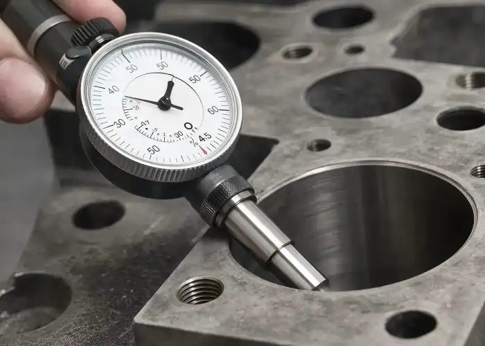
1.Calipers
Calipers are one of the most common measuring tools used in machining and quality inspection. They can measure external dimensions, internal diameters, and depths, making them useful for quick checks during production. When measuring holes, the inside jaws of the caliper expand to contact the inner walls of the bore and provide a direct reading.
Calipers are best suited for general measurements where extremely tight tolerances are not required. They are often used for inspecting larger holes or verifying approximate dimensions before more precise measurements are performed. Although calipers are convenient and fast, their accuracy is typically lower than specialized internal measuring tools.
2.Micrometers
Inside micrometers are precision measuring instruments designed specifically for internal diameter measurement. They provide higher accuracy than calipers and are commonly used when tight tolerances must be verified. The tool uses adjustable measuring rods or extensions that expand inside the hole until they contact the bore surface.
Because of their high precision, inside micrometers are often used in controlled inspection environments such as quality control laboratories or final product verification. They are widely applied in aerospace components, precision mechanical parts, and high-accuracy assemblies. Proper handling and calibration are important to ensure consistent measurement results and avoid operator errors.
3.Bore Gauges
Dial bore gauges are widely used in machining and inspection to measure internal diameter with high accuracy. The gauge is inserted into the hole and moved slightly back and forth to find the smallest diameter reading, which represents the true bore size. This method helps detect variations in roundness, taper, or slight deformation inside the hole.
Bore gauges are particularly useful for medium to tight tolerance holes where dimensional accuracy is critical. They are commonly used in engine cylinders, bearing seats, and precision machined housings. Because they provide repeatable and reliable measurements, dial bore gauges are a standard tool in many CNC machining workshops.
4.Coordinate Measuring Machine
A Coordinate Measuring Machine (CMM) is an advanced inspection system used for highly accurate dimensional measurement. The machine uses a probing system to measure points on a part and digitally calculate dimensions, geometry, and feature locations. This allows precise inspection of complex parts that require strict tolerance control.
CMM systems can measure hole diameter, position tolerance, perpendicularity, and concentricity relative to other features. Because of their high precision and data recording capability, CMMs are widely used in aerospace, automotive, and precision manufacturing industries. They play an important role in quality assurance and help verify that parts meet exact design specifications.
5.Split Ball Gages
Split ball gages are specialized measuring tools used for inspecting small internal bores, especially when access is limited. The tool contains a split spherical measuring head that expands slightly inside the hole. Once adjusted to fit the bore, the dimension can be measured using an external micrometer.
These gauges are particularly useful for narrow or blind holes where conventional bore gauges may not fit. Split ball gages are commonly used in precision machining, toolmaking, and inspection of small mechanical components. Their compact design allows accurate measurement in confined spaces while maintaining good repeatability for small diameter holes.
Engineering Considerations When Choosing Hole Types
1. Load Distribution
Holes used in structural parts must distribute mechanical loads without creating excessive stress concentration. When a hole is introduced into a component, it removes material and changes how forces flow through the structure. Engineers must consider factors such as hole diameter, edge distance, and surrounding wall thickness to prevent cracking or deformation under load.
If the hole is too close to an edge or the material around it is too thin, the component may fail prematurely. Proper hole design ensures that loads are evenly transferred across the part, maintaining structural strength and long-term reliability.
2. Alignment Requirements
In assemblies that require precise positioning, hole alignment becomes extremely important. Components such as dowel pins, shafts, and precision fasteners rely on accurately positioned holes to maintain correct orientation between parts.
Even small positional errors can cause cumulative misalignment when multiple components are assembled together. This may lead to vibration, increased wear, or difficulty during installation. To avoid these issues, engineers often specify tight positional tolerances using GD&T. Accurate machining and inspection ensure that holes align correctly and maintain consistent assembly performance.
3. Corrosion Exposure
In harsh or corrosive environments, hole geometry can trap moisture, chemicals, or debris. These trapped contaminants may accelerate corrosion inside the hole, gradually weakening the surrounding material. This is especially important for components used in marine, chemical processing, or outdoor equipment.
Designers often consider protective strategies such as improved drainage paths, protective coatings, or corrosion-resistant materials. Surface treatments like anodizing, plating, or passivation can also help protect internal hole surfaces. Proper hole design helps reduce long-term degradation and improves the durability of the overall component.
4. Manufacturing Cost
Hole design can significantly influence manufacturing cost and production efficiency. Simple holes with moderate tolerances can be produced quickly using standard drilling operations. However, complex hole features such as deep holes, threaded holes, or extremely tight tolerances require more machining time and specialized tooling.
Additional processes such as reaming, honing, or precision inspection may also increase cost. Engineers must balance performance requirements with manufacturing practicality. Optimizing hole design early in the design stage helps reduce machining complexity while still maintaining the required functionality.
5. Tool Accessibility
Some hole locations may be difficult to reach with standard machining tools. Limited tool access can occur when holes are positioned inside deep cavities, near walls, or at unusual angles. These conditions may require longer tools, specialized fixtures, or multi-axis machining equipment.
Poor accessibility can reduce machining stability and increase setup complexity. It may also affect dimensional accuracy and surface finish quality. Designers should consider tool accessibility during the design stage to ensure that holes can be machined efficiently and reliably using available CNC machining processes.
6. Chip Evacuation
Chip evacuation is an important factor in hole machining, especially for blind holes and deep holes. During drilling, chips must be removed continuously from the cutting zone to prevent blockage and excessive heat buildup.
If chips accumulate inside the hole, they may damage the cutting tool or scratch the hole surface. This can reduce dimensional accuracy and surface quality. Machinists often use techniques such as peck drilling or high-pressure coolant to improve chip removal. Effective chip evacuation helps maintain stable cutting conditions and ensures consistent hole quality.
7. Common Hole Manufacturing Problems
Even when machining parameters are properly set, problems may still occur during hole production. Many issues are related to tool wear, incorrect cutting speeds, unstable workpiece clamping, or poor chip evacuation. These factors can gradually affect hole accuracy and surface quality.
If problems are not detected early, they may lead to dimensional errors that affect assembly performance. Regular tool inspection, stable fixturing, and proper machining parameters help reduce these risks. Understanding common machining problems allows manufacturers to improve process stability and maintain consistent product quality.
8. Burr Formation
Burrs are small sharp edges that form around the entrance or exit of a drilled hole. They usually appear when the cutting tool becomes dull or when feed rates are not properly controlled. Burrs may also form when the drill exits the material and pushes metal outward.
Although burrs are small, they can cause assembly problems or safety issues if not removed. Deburring processes such as manual finishing, chamfering, or automated deburring tools are often used to remove these sharp edges and improve overall part quality.
9. Tolerance Drift
Tolerance drift occurs when the hole diameter gradually moves out of specification during production. This is often caused by tool wear, heat buildup, or changes in cutting conditions during long machining cycles.
As the cutting tool wears down, it may remove less material, causing the hole size to become slightly smaller or inconsistent. If not monitored, this variation can lead to assembly problems. Regular tool replacement, process monitoring, and statistical quality control help maintain stable tolerances throughout production runs.
10. Misalignment
Hole misalignment occurs when the drilled hole deviates from its intended position or direction. This can happen if the workpiece is not clamped securely, if the machine lacks rigidity, or if the drill deflects during cutting.
Misaligned holes may cause assembly difficulties, especially in parts that require precise alignment with other components. To prevent this issue, machinists ensure proper fixturing, machine stability, and correct cutting parameters. Accurate setup and inspection procedures help maintain hole position accuracy during machining.
11. Ovality
Ovality occurs when a hole becomes slightly oval instead of perfectly round. This problem is often caused by vibration, excessive cutting forces, or tool deflection during drilling operations.
When ovality occurs, the hole may not fit properly with shafts, bearings, or other mating components. This can affect mechanical performance and increase wear during operation. Maintaining stable machining conditions, selecting proper cutting parameters, and using rigid tooling help reduce the risk of oval hole formation.
12. Poor Surface Roughness
Poor surface roughness inside a hole can reduce component performance, especially in applications involving rotation, sealing, or load transfer. Rough internal surfaces may increase friction, cause premature wear, or affect sealing performance.
This problem often occurs when cutting parameters are not optimized or when coolant flow is insufficient. Proper tool selection, correct cutting speeds, and adequate lubrication help improve surface finish quality. In precision applications, additional processes such as reaming or honing may be used to achieve smoother internal surfaces.
Common Methods for Machining Holes
Once hole types are understood, the next question is: how are they produced? The machining method selected directly affects dimensional accuracy, surface finish, tool life, and production efficiency. Different hole geometries, materials, and tolerance requirements demand different machining strategies. The most common hole machining methods include:
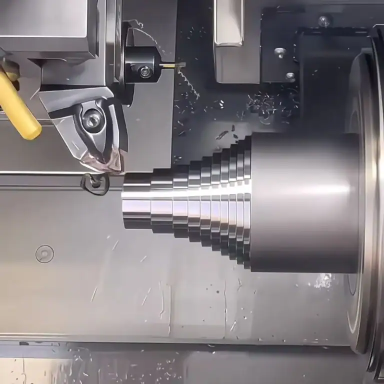
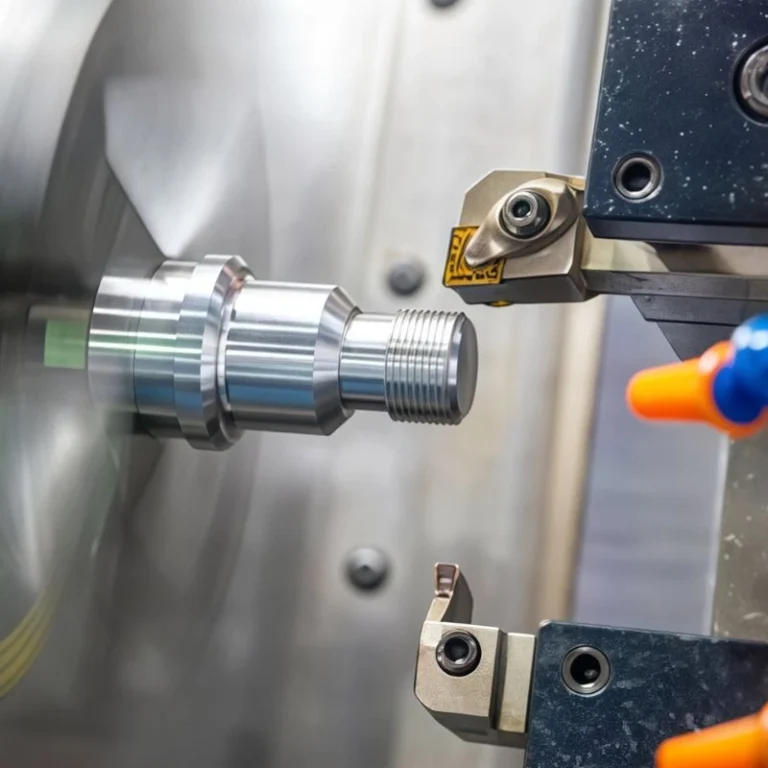
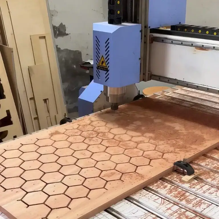
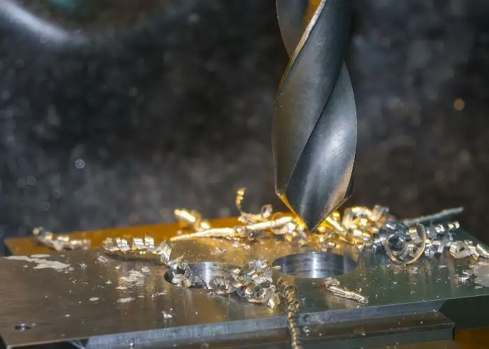
1. CNC Drilling
CNC drilling is the most common method used to produce standard cylindrical holes in machining. A rotating drill bit removes material along the axial direction to create through holes or blind holes quickly and efficiently. This process works well with many materials, including aluminum, steel, and plastics.
CNC drilling is widely used in both prototype and mass production because it offers high speed and good productivity. While drilling provides reliable results for general applications, its dimensional accuracy and surface finish are usually moderate compared with finishing operations such as reaming.
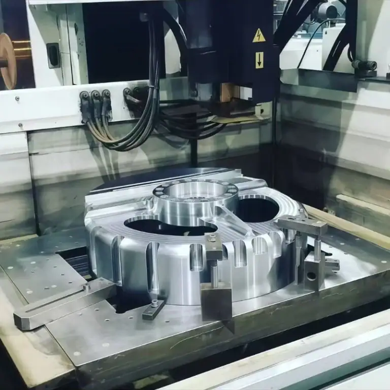
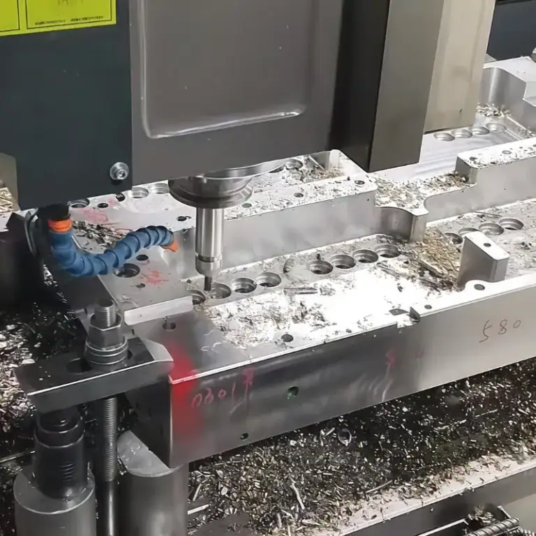
2. CNC Milling
CNC milling can also be used to produce holes, especially when larger diameters or non-standard shapes are required. Instead of drilling straight down, the milling tool can move along a programmed circular path, a process known as circular interpolation.
This method provides greater flexibility and better positional control compared with traditional drilling. CNC milling is often used when hole location accuracy is critical or when the hole size exceeds the available drill diameter. It is also useful for producing slots, pockets, or complex hole geometries in precision mechanical parts.
3. EDM
Electrical Discharge Machining (EDM) is a non-traditional machining method that removes material using controlled electrical sparks. Because the process does not rely on mechanical cutting forces, EDM is particularly suitable for machining hardened materials and very small holes.
EDM is commonly used in mold manufacturing, aerospace components, and precision tooling. It can create complex internal geometries that would be difficult to achieve with conventional cutting tools. However, EDM is generally slower than traditional machining methods and is typically used when high precision or special material conditions are required.
4. Reaming
Reaming is a finishing process used after drilling to improve hole accuracy and surface quality. A reamer removes a small amount of material from the drilled hole to achieve tighter diameter tolerances and a smoother internal surface.
Because the reamer follows the existing drilled hole, it does not significantly change hole position but refines the final size and finish. Reamed holes are commonly used in applications requiring precise alignment, such as dowel pin holes, bearing seats, and precision mechanical assemblies where consistent fit and dimensional accuracy are important.
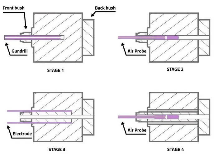
5.Deep Hole Drilling
Required for holes with high length-to-diameter ratios (typically L/D > 10). Standard drilling methods become unstable at greater depths due to chip evacuation and heat buildup challenges.
Machining method selection depends on material type, required tolerance, hole depth, diameter, and production volume. Process stability, coolant delivery, and tool rigidity must be considered to maintain consistent quality.
Deep hole drilling involves specialized equipment, high-pressure coolant systems, and enhanced chip evacuation strategies, which will be discussed in the next section.
FAQs
Which type has holes?
Many mechanical components contain holes as functional features used for fastening, alignment, or fluid passage. Examples include brackets, plates, machine housings, and structural frames. In engineering and machining, holes may be drilled, tapped, reamed, or counterbored depending on the design requirement. These hole features allow bolts, shafts, dowel pins, or pipes to pass through or connect different parts within an assembly.
What are the standard hole classifications in engineering?
In engineering, holes are usually classified based on geometry and function. Common categories include simple holes, through holes, blind holes, threaded holes, and precision holes such as reamed holes. Additional types include stepped holes like counterbore or countersink holes, and special features such as deep holes or interrupted holes. These classifications help engineers select the appropriate hole type depending on assembly requirements and manufacturing processes.
What are the different types of bolt holes?
Bolt holes are designed to accommodate bolts used in mechanical or structural assemblies. The most common types include clearance holes, threaded holes, counterbore holes, and countersink holes. Clearance holes allow the bolt to pass freely through the part, while threaded holes hold the bolt directly. Counterbore holes create space for bolt heads to sit below the surface, and countersink holes allow flat-head screws to sit flush with the surface.
How to determine clearance hole diameter and tolerance?
The diameter of a clearance hole is typically determined by the size of the bolt or screw used in the assembly. Engineers usually follow standard tables such as ISO or ANSI clearance hole charts. Clearance holes may be classified as close fit, normal fit, or loose fit depending on assembly precision requirements. Proper tolerance selection ensures that the fastener can pass through easily while still maintaining accurate alignment between connected parts.
What are the different types of boring holes?
Boring holes are holes that are enlarged or finished using a boring tool after an initial drilling operation. Common types include precision bored holes, stepped bored holes, and alignment bores. Boring is used when high dimensional accuracy, improved roundness, or better surface finish is required. This process is widely applied in engine cylinders, bearing housings, and other precision mechanical components where tight tolerances must be maintained.
Conclusion
Understanding the 16 types of holes in engineering and machining provides a foundation for better design, manufacturing accuracy, and assembly reliability. From simple through holes to deep precision bores, hole geometry, tolerance, machining method, and measurement strategy must align with application requirements.
At TiRapid can provide manufacturing guidance and production solutions tailored to your specifications. Correct hole selection and machining control directly influence performance, cost efficiency, and structural integrity in modern CNC manufacturing.