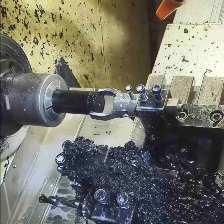
Thin wall machining is one of the most challenging processes in CNC manufacturing. Its core difficulty lies in insufficient part rigidity, which easily leads to vibration, deformation, and precision deviation. The key to solving this problem lies in proper tool selection, optimized cutting parameters, specialized fixture design, and the implementation of vibration-damping support technology. This article will focus on the key technologies, common challenges, and corresponding solutions for thin-wall machining , providing a comprehensive understanding of thin-wall machining.
What Is Thin-Wall Machining
Thin-wall machining refers to the process of precision cutting thin-walled, complex, and rigid parts. Generally speaking, parts are classified as thin-walled when their wall thickness is less than 2 mm or when their height-to-wall-thickness ratio (H/T) is greater than 10.
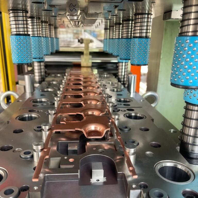
In my actual processing projects, the proportion of parts involving thin-walled parts exceeds 20%, especially in the aerospace, automotive lightweight, medical equipment and consumer electronics industries. They have extremely high requirements for weight and strength, and thin-wall design has almost become standard.
Why is the demand for thin-walled parts continuing to grow ? The key lies in the trend toward lightweighting and improved performance . In the aerospace industry, for example, according to the International Air Transport Association (IATA), every kilogram reduced in aircraft structure can save approximately $3,000 in fuel costs annually. In the new energy vehicle industry, a 10% weight reduction can increase vehicle range by 6–8%. This means designers and manufacturers must increasingly utilize thin-walled structures to reduce weight and improve energy efficiency while maintaining sufficient strength and rigidity.
Therefore, thin-wall machining is not just a processing technology, but also a capability that is oriented towards future manufacturing trends. When processing thin-walled parts, I often need to comprehensively consider the rationality of part design, fixture support scheme, and tool selection. Through data-driven parameter optimization, I ensure processing stability and precision, ensuring that it meets the industry’s strict requirements for lightweight and high performance.
Core Challenges Of Thin-Wall Machining
Thin-wall machining lies in the inherent lack of workpiece rigidity. This directly leads to deformation, vibration, and thermal stress accumulation during the cutting process, ultimately compromising dimensional accuracy and surface quality. In my actual machining projects, statistics show that the rework rate for thin-walled parts is approximately 30%–40% higher than that for conventional structural parts. This is primarily due to the failure to effectively control these challenges.
First of all, the lack of workpiece rigidity is the most direct problem. When the cutting force acts on the thin-walled area, the part will undergo elastic and plastic deformation, resulting in dimensional deviations beyond the tolerance range. Secondly, cutting heat and residual stress cannot be ignored, especially for materials such as aluminum alloys and titanium alloys. Local thermal expansion is prone to occur during long-term cutting, and warping often occurs after the workpiece cools down, affecting assembly accuracy. In addition, during high-speed processing, thin-walled parts are prone to resonance and chatter marks, which not only destroys the surface finish, but also accelerates tool wear. Finally, there is a natural contradiction between surface quality and processing efficiency: in order to prevent deformation, the cutting depth and feed rate must be reduced, but this will extend processing time and increase costs.
Therefore, when working with thin-walled parts, I typically prioritize fixture optimization, fine-tuning cutting parameters, and toolpath planning. I use a data-driven approach to assess deformation risks and, when necessary, employ auxiliary supports or segmented machining strategies to reduce errors. While these challenges are significant, they can be gradually overcome through systematic process optimization.
Process Design Principles For Thin-Wall Machining
In thin-wall machining is process design optimization from the outset, rather than relying solely on ad hoc adjustments during the machining process. In my experience, projects that consider thin-wall properties and develop appropriate processes during the design phase generally achieve a 25%–35% higher first-pass yield. This demonstrates that proactively optimizing part structure, fixture selection, and tool paths is crucial for controlling deformation and improving machining efficiency.
Part
design phase, I prioritize increasing local rigidity by adding reinforcing ribs and rationally distributing support areas. For extremely thin walls, I often employ temporary support structures—retaining auxiliary ribs during machining and removing them after forming—to reduce the risk of deformation. Statistics show that this type of design can reduce part deformation by approximately 40%.
Fixture And Clamping Technology
Fixture selection is also crucial. Traditional mechanical fixtures can easily cause localized stress concentrations when machining thin-walled parts, leading to deformation. To address this, I prefer vacuum fixtures for uniform force distribution or flexible support fixtures to accommodate complex part curves. For complex, thin-walled parts in mass production, I typically develop specialized fixtures to ensure repeatable and reliable clamping.
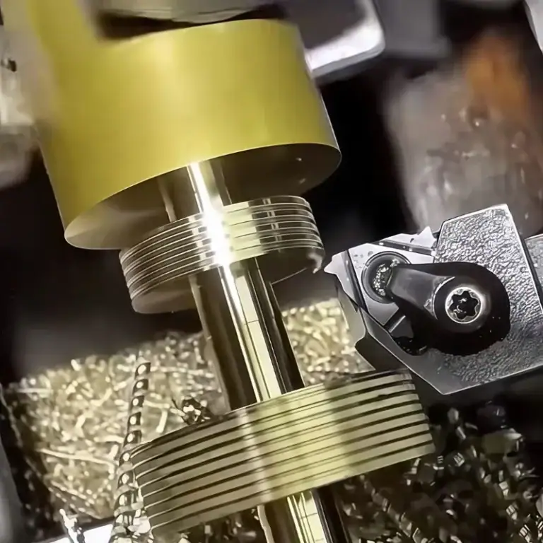
Tool Selection And Cutting Path
planning, I generally prioritize sharp, low-resistance cutting tools to minimize workpiece deformation. Climb milling can significantly reduce cutting forces and improve surface quality. Furthermore, I often use segmented path planning to disperse stress and heat distribution, avoiding localized thermal deformation caused by long, continuous cutting across the entire surface. Practice has shown that proper path planning can reduce vibration and deformation by approximately 30%.
Overall, the stability of thin-wall machining isn’t the result of optimizing a single process , but rather a systematic combination of structural design, fixture support, and toolpath planning . Through data-driven verification and accumulated experience, I can usually control deformation within an acceptable range during the first trial cut, thus ensuring stability and consistency in subsequent mass production.
Parameter Optimization For Thin-Wall Machining
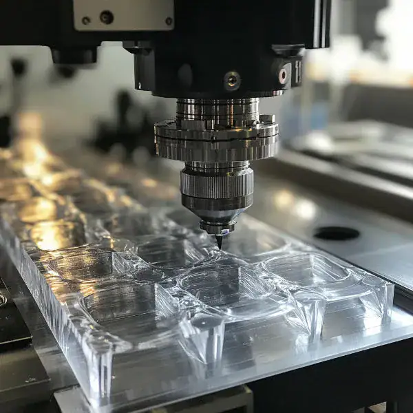
When machining thin-walled parts, optimizing cutting parameters significantly impacts process stability. Based on my experience machining thin-walled parts made of metals ( aluminum alloys, stainless steel, copper ) and engineering plastics (POM, PEEK, PVC) , using appropriate speeds, feeds, and tool selection can effectively control wall surface deviations within ±0.02 mm and achieve a surface roughness of Ra 0.6 μm .
The following table gives typical parameter ranges and their advantages:
| Parameter Category | Recommended range (typical materials) | Advantages |
| Cutting speed (Vc) | Aluminum alloy: 250–350 m/min POM: 500–800 m/min |
High-speed milling reduces cutting forces and improves surface quality |
| Feed rate (fz) | Aluminum alloy: 0.05–0.12 mm/z POM: 0.10–0.25 mm/z |
High feed strategy improves machining efficiency and avoids built-up edge |
| Depth of cut (ap) | Generally ≤0.5 mm (thin wall) | Small cutting depth can reduce cutting force and reduce wall deformation |
| Cutting width (ae) | 20%–40% tool diameter | Layered processing reduces stress and heat buildup |
| Tool diameter | Commonly used Ø4–Ø12 mm necking tools | Reduce interference, suitable for processing in narrow areas |
| Tool coating | TiAlN or AlTiN coating | Improve wear resistance, enhance heat dissipation capacity, suitable for high temperature alloy materials |
Actual Effect (Aluminum Alloy vs POM)
Under this parameter combination, the wall deformation of aluminum alloy thin-walled parts can be controlled within 0.01-0.02 mm , and the first-time pass rate is increased by 30% .
Due to the high material flexibility and low cutting resistance of POM thin-walled parts , the use of high-speed and high-feed strategies can increase processing efficiency by 20-30% , reduce surface melting, and stabilize tool life.
Ra 0.8–1.0 μm after fine machining , meeting the conventional requirements of electronic and electrical housing parts.
Heat And Stress Control
In thin-walled part machining, heat buildup and residual stress are key factors contributing to deformation. When working with aerospace and medical-grade thin-walled parts, I’ve observed that neglecting heat and stress management can lead to part warpage of 0.05–0.1 mm, even impacting subsequent assembly accuracy. By properly selecting cooling methods, optimizing the machining sequence, and employing stress relief processes, the risk of deformation can be significantly reduced, dimensional deviations within ±0.02 mm, and consistent surface finishes of Ra 0.8–1.2 μm can be achieved.
When Choosing A Cooling Method,
I typically prefer high-pressure coolant (50–70 bar). This effectively dissipates cutting heat and facilitates chip removal, making it particularly suitable for machining materials with poor thermal conductivity, such as titanium and stainless steel. When milling soft materials like aluminum at high speeds, I prefer minimum quantity lubrication (MQL). This not only reduces tool wear but also lowers machining temperature by 15–20%. Based on project statistics, the right cooling method can extend tool life by 20–30%.
Processing
also directly affects the stress relief effect. I typically use a staged process: roughing – stress relief – semi-finishing – finishing. After roughing, I leave a 0.3–0.5 mm stock, then perform natural aging or low-temperature annealing before finishing. This process arrangement can reduce part warpage by over 40%.
Heat
treatment (T6, T651, etc.) to eliminate internal stresses. For precision structural parts that can’t be treated at high temperatures, vibration aging (VSR) or thermal shock stress relief (TSR) are options. These physical stress relief methods can reduce residual stress by 60–80%, ensuring the long-term stability of thin-walled parts after machining.
The combined application of these heat and stress control strategies has enabled me to significantly reduce part rework rates in actual production and effectively improve the delivery consistency and long-term reliability of thin-walled parts.
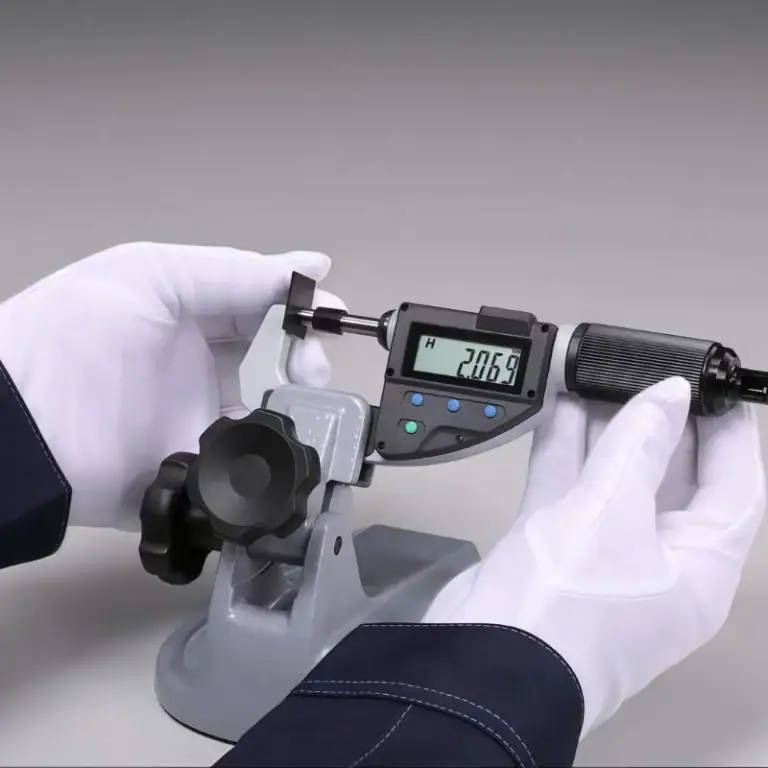
High-Precision Processing And Testing
The machining of thin-walled parts places extremely high demands on dimensional accuracy and surface quality, especially in the aerospace and medical device industries. Tolerances of ±0.01–0.02 mm and surface roughness of Ra 0.8 μm or better are often required. Meeting these standards is difficult to guarantee with traditional empirical parameters alone. Therefore, in production, I employ real-time monitoring, adaptive control, and online measurement and compensation to ensure a more stable and controllable machining process.
Real-Time Monitoring And Adaptive Control.
By integrating cutting force sensors and vibration monitoring modules into the machine tool system, we can capture load changes during the cutting process in real time, allowing the CNC system to automatically adjust feed and spindle speed. This adaptive control strategy can reduce cutting force fluctuations by 15%–25%, significantly reducing wall deviations caused by vibration and tool wear. Furthermore, real-time monitoring can promptly identify abnormal conditions, preventing tool breakage and workpiece scrapping.
on-machine probe systems (such as Renishaw or Blum) to perform online inspection of critical dimensions and dynamically compensate them through the CNC system. This process avoids cumulative errors caused by thermal deformation or machine tool drift, reducing dimensional deviations in the final product by over 30%. For batch production of thin-walled parts, this online measurement solution can consistently increase the first-pass yield to over 95%, significantly reducing subsequent manual inspection and rework time.
Comparison Of Commonly Used High-Precision Machining And Testing Methods
| Technical methods | Features | Improved performance |
| Real-time cutting force monitoring | Real-time detection of cutting forces and automatic adjustment of parameters | Cutting force fluctuations are reduced by 15%–25%, reducing the risk of wall deformation |
| Adaptive feed control | Dynamically adjust feed rate based on load and tool status | Improved machining stability and 10%–20% longer tool life |
| In-machine online probe system | Directly detect key dimensions during processing and provide feedback for compensation | Dimensional deviation is reduced by more than 30%, reducing secondary clamping errors |
| Dynamic error compensation | Automatically correct errors caused by thermal drift and machine deformation | The first batch qualified rate can be stabilized at more than 95% |
Through real-time monitoring and online compensation technology, thin-wall machining can not only achieve extremely high precision standards, but also ensure processing consistency and production efficiency. It is an indispensable key link in modern manufacturing.
Typical Application Cases Of Thin-Wall Machining
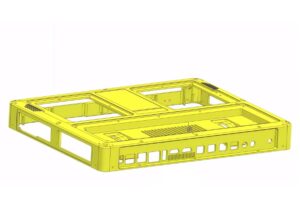
Thin-wall machining is widely used in industries with extremely high demands on weight, precision, and structural complexity. According to my project statistics, thin-walled parts account for approximately 20%–30% of all precision machining tasks, with aerospace, medical devices, and consumer electronics being the primary applications.
| Industry Applications | Material and structural characteristics | Processing requirements and typical parameters |
| Aerospace thin-walled parts | Aluminum alloy (6061-T6, 7075-T6), POM, PEEK, wall thickness 0.5–1.0 mm | ±0.02 mm dimensional accuracy, Ra 0.8–1.2 μm surface quality |
| Medical equipment parts | Stainless steel (316L), POM, PVC
,PC, titanium alloy (Ti6Al4V) shell |
High precision (±0.015 mm), burr-free, polished |
| Consumer electronics | Aluminum-magnesium alloy structural parts and appearance parts, wall thickness 0.6–1.2 mm | Ra 0.6–1.0 μm, anodized or sandblasted surface finish |
These cases demonstrate that thin-wall machining isn’t limited to a single part type, but encompasses a wide range of applications, from aerospace structures to everyday consumer goods. In practice, I’ve found that while the applications vary, their shared characteristics of lightweight design, high precision, and aesthetically pleasing surfaces make thin-wall machining technology highly versatile.
Energy Saving And Sustainable Processing
In thin-wall machining , energy conservation and sustainability are gradually becoming important components of corporate competitiveness. In the past, we tended to focus on machining accuracy and production efficiency, but with the manufacturing industry’s transition to green, how to reduce energy consumption and extend tool life while ensuring product quality has become a core issue that must be addressed.

Multi-objective optimization: balance of quality, efficiency and energy consumption
I will conduct multi-objective optimization, comprehensively considering the balance between quality, efficiency and energy consumption. For example, in high-speed milling, by adjusting the spindle speed and feed rate, unnecessary energy loss can be reduced while ensuring surface quality; at the same time, through reasonable tool path planning and batch processing sequence optimization, the air cutting time and auxiliary time can be further shortened, and the overall processing efficiency can be improved by 8%–12% .
Green Manufacturing Concepts And Improved Tool Life:
Green manufacturing not only involves energy conservation during machining but also includes the use of environmentally friendly cooling and lubrication technologies (such as minimal quantity lubrication (MQL)). For example, in a project involving thin-walled aluminum alloy parts, the implementation of minimal quantity lubrication not only controlled cutting heat and friction but also reduced coolant consumption by 80% , achieving a near-dry machining effect.
Furthermore, the use of coated tools (such as TiAlN and AlTiN) and optimized tool geometry significantly reduce cutting forces and frictional heat, thereby extending tool life and reducing tool scrapping. Over the long term, these measures can eliminate hundreds of tool changes annually, lowering both manufacturing costs and solid waste emissions.
FAQs
What Is The Thin Wall Machining Technique
Thin Wall Machining Is A Specialized CNC Process Focused On Components With Wall Thickness Typically Less Than 2 mm Or An H/T Ratio Greater Than 10. I Use Low Cutting Forces, Multi-Pass Strategies, And Specialized Fixtures To Reduce Deformation. This Technique Is Essential In Aerospace And Medical Industries, Where ±0.02 mm Accuracy And Ra 0.8 µm Surface Quality Are Required.
What Is The Minimum Wall Thickness For Machining
The Minimum Wall Thickness Depends On Material And Design Requirements. For Aluminum Alloys, I Regularly Machine Walls As Thin As 0.4–0.5 mm Using High-Speed Milling And Rigid Fixtures. For Titanium Or Stainless Steel, Practical Limits Are Around 0.7–1.0 mm Due To Material Strength And Cutting Force. These Thicknesses Ensure Dimensional Stability And Minimize Vibration-Induced Defects.
Is There A Way To Fix Thin Walls
Yes, I Use Multiple Strategies To Stabilize Thin Walls During Machining. Temporary Support Ribs Or Tabs Are Added During Design And Removed After Finishing. Vacuum Fixtures Or Conformal Soft Jaws Distribute Clamping Force Evenly. Optimized Parameters—Such As 0.5 mm Depth Of Cut And High Feed Rates—Reduce Cutting Forces, Preventing Wall Deflection. These Methods Improve Accuracy By 30–40% In Production.
What Is A Thin Wall In Engineering
In Engineering, A Thin Wall Refers To A Structure Whose Thickness Is Small Relative To Its Height Or Diameter, Typically An H/T Ratio Above 10 Or Wall Thickness Less Than 2 mm. I Encounter Thin Walls In Aerospace, Automotive, And Medical Devices Where Lightweight, High-Strength Designs Are Required. Such Parts Demand Special Toolpaths And Fixtures To Achieve ±0.02 mm Tolerances Reliably.
What Does Thin Wall Mean
Thin Wall Means A Structural Feature With Low Thickness Compared To Its Overall Dimensions, Making It Flexible And Prone To Deformation Under Cutting Forces. I Classify Parts As Thin Wall When Thickness Falls Below 2 mm Or The H/T Ratio Exceeds 10. This Definition Guides My Approach To Select Proper Cutting Tools, High-Speed Milling, And Fixture Designs To Maintain Geometric Accuracy.
What Is The Criteria For A Thin Wall
The Common Criteria For Thin Walls Include Thickness Less Than 2 mm Or An H/T Ratio Greater Than 10:1. I Also Consider Material Modulus And Stiffness When Determining If A Part Qualifies As A Thin Wall. In Aluminum Aerospace Housings, Even 1.5 mm May Be Rigid Enough, While Titanium Often Requires 2 mm For Stability. These Metrics Help Me Plan Suitable Machining Strategies.
Conclusion
Thin-wall machining may seem complex, but through proper design , fixture selection , parameter optimization , material selection, and real-time testing, high precision and stability can be achieved. If you’re designing or producing thin-walled parts, don’t be intimidated by the challenges. Mastering these key technologies will not only ensure product quality and lightweight performance, but also help your company stand out from the competition and move towards a greener, more efficient manufacturing future.