Surface Roughness Chart is one of the most useful references for understanding surface finish, comparing roughness values, and linking drawing requirements with real manufacturing decisions. It helps engineers, buyers, and production teams interpret surface quality more clearly, evaluate measurement standards, and choose finish requirements that match part function, process capability, and cost expectations.
In this guide, the main symbols, values, measurement methods, and selection principles are explained for engineering, CNC machining, and production applications.
What Is A Surface Roughness Chart?
A surface roughness chart is a reference tool used to compare surface finish values, symbols, and measurement parameters. It helps engineers, buyers, and manufacturers understand roughness levels and choose suitable finishes for different machining and manufacturing applications.
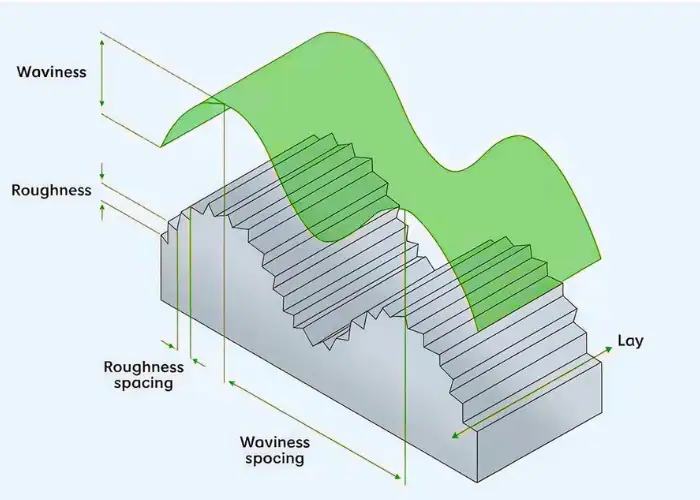
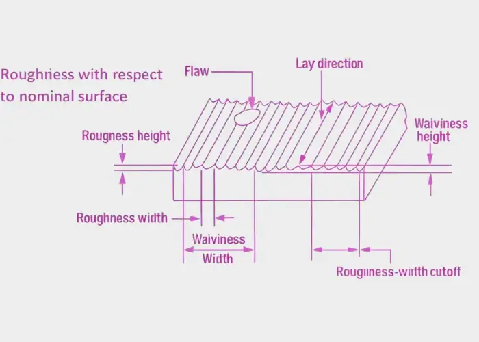
To use a surface roughness chart correctly, it is also necessary to understand what surface roughness, waviness, and lay actually mean in engineering practice. Surface roughness is different from waviness and lay. Roughness describes the small-scale texture, waviness refers to larger and more widely spaced deviations, and lay describes the main direction of the surface pattern.
This distinction matters because roughness directly affects fit, sealing, friction, wear, coating behavior, and appearance. In engineering practice, surface roughness is often a functional requirement rather than only a visual one.
Why Surface Roughness Matters In Engineering And Manufacturing?
Surface roughness matters because it directly affects how a part fits, seals, slides, wears, and performs in real use. In engineering and manufacturing, the right roughness requirement helps balance function, quality, machining cost, and production efficiency.
A rougher surface may increase friction, leakage risk, and wear, while a smoother surface may improve contact quality and appearance. However, smoother does not always mean better if the application does not actually require it.
In production, surface roughness also affects machining time, tool condition, and manufacturing cost. A finish requirement that is tighter than necessary may add cost without improving the real function of the part.
Surface Roughness Parameters Explained
Surface roughness is described with several parameters, and each one highlights a different feature of the surface profile. Understanding what these values mean is important before comparing finishes, reading charts, or applying roughness requirements in engineering drawings.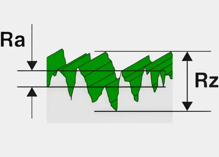
1. Ra Surface Roughness
Ra is the most commonly used roughness parameter in engineering drawings, machining standards, and inspection reports. It represents the arithmetic average of the absolute profile deviations from the mean line over the evaluation length, which makes it a practical way to describe the general smoothness of a surface.
Because Ra is simple, widely recognized, and easy to compare across processes, it is often used for general finish control in machining. It works well when the goal is to specify a consistent average surface condition rather than focus on isolated peaks or valleys.
2. Rz Surface Roughness
Rz measures the average height difference between the highest peaks and the deepest valleys within the sampling length. Compared with Ra, it gives more attention to local extremes, which makes it useful when surface contact behavior matters more than the general average finish.
Rz is often applied in situations where sealing performance, surface contact, or local functional behavior is more important than overall appearance. Even when two surfaces have a similar Ra value, their Rz values may still be different enough to affect how the part performs in actual use.
3. Rt And Rmax
Rt refers to the total height of the roughness profile across the full evaluation length, while Rmax usually indicates the maximum single peak-to-valley height found in the measured sampling area. These parameters focus more on the largest irregularities present on the surface.
They are especially useful when isolated extremes can affect performance, such as in sealing, sliding contact, or parts sensitive to scratches, deep valleys, or sharp peaks. In these cases, average roughness alone may not fully describe the true functional condition of the surface.
4. RMS Surface Roughness
RMS, often written as Rq, is the root mean square value of the surface deviations. It is calculated differently from Ra and gives more weight to larger deviations, which means it responds more strongly to bigger surface irregularities.
RMS is sometimes seen in legacy drawings, older standards, or industry-specific specifications. Although it is related to Ra, the two values are not identical and should not be substituted without checking the actual standard or requirement used in the drawing or inspection method.
5. Key Differences Between Ra, Rz, Rt, And RMS
Ra shows average roughness, Rz reflects average peak-to-valley height, Rt shows total profile height, and RMS emphasizes larger deviations through a different calculation method. Each parameter describes a different aspect of the surface profile rather than simply repeating the same information.
The correct parameter depends on the application and what the surface must actually do. Some parts only need general finish control, while others need better insight into local extremes, sealing behavior, contact performance, or the possible presence of deeper valleys and sharper peaks.
Surface Roughness Units And Value Interpretation
Surface roughness values are usually expressed in micrometers (µm) or microinches (µin), and reading them correctly is essential in machining and manufacturing. Lower values usually mean smoother finishes, while higher values indicate rougher surfaces with more visible tool marks.
Common Ra values include 0.8, 1.6, 3.2, and 6.3µm. In practice, these numbers should not be judged alone, because the correct finish still depends on part function, material, machining process, and production cost.
For example, Ra 0.8 is finer than Ra 3.2. A lower value may improve sealing or appearance, but it can also increase machining time and cost if the application does not actually require it.
Common Surface Roughness Values Used In CNC Machining
Common surface roughness values in CNC machining are usually selected according to part function, surface importance, and manufacturing cost. The reference below shows how common Ra levels are typically used on sealing faces, fitting areas, general machined surfaces, and lower-priority features:
| Ra Value | Finish Level | Typical Use In CNC Machining |
| Ra 0.8 | Fine | Sealing surfaces, precision fitting areas, higher-quality visible surfaces |
| Ra 1.6 | Medium-fine | General functional surfaces, precision housings, mating features |
| Ra 3.2 | General | Standard machined parts, outer faces, non-critical interfaces |
| Ra 6.3 | Rough | Structural areas, support faces, low-priority machined surfaces |
Surface Roughness Chart
A surface roughness chart provides a practical reference for comparing finish levels, converting units, and matching roughness requirements with realistic manufacturing capability. It also helps engineers and buyers read values more clearly and choose finishes that fit both function and production needs.
The table below shows common surface roughness levels, unit conversion, typical use, and machining reference:
| Surface Finish Quality | Ra (µm) | Ra (µin) | Typical Appearance | Typical Use | Common Process Reference |
| Very Fine | 0.2 | 8 | Very smooth, polished-like | Precision sealing or very fine functional surfaces | Fine Grinding |
| Fine | 0.4 | 16 | Smooth precision finish | High-quality machined finish | Fine Grinding / Reaming / Fine Turning |
| Standard Fine | 0.8 | 32 | Controlled machined finish | Precision parts and controlled interfaces | Fine Grinding / Fine Turning / EDM |
| Medium | 1.6 | 63 | General engineering finish | Common engineering surfaces | Reaming / Fine Turning / Standard Milling |
| General | 3.2 | 125 | Visible tool marks | Standard machined parts | Standard Milling |
| Rough | 6.3 | 250 | Coarser machining texture | Rougher machining or non-critical areas | Rough Milling / Rough Turning / EDM |
| Very Rough | 12.5 | 500 | Heavy tool marks or rough process finish | Coarse finish before later processing | Heavy roughing or pre-finish surfaces |
Surface Roughness Parameters Reference
| Parameter | Meaning | Best Use |
| Ra | Arithmetic average roughness | General finish specification |
| Rz | Average peak-to-valley height | Functional contact and sealing review |
| RMS / Rq | Root mean square roughness | Legacy specs or special standards |
| Rt | Total roughness height | Extreme surface evaluation |
Surface Finish Symbols And Drawing Callouts
Surface finish symbols and drawing callouts are essential because they show where a finish requirement applies and how that surface should be controlled. They also help communicate whether machining, material removal, or a specific roughness value is required for the part.
Surface Finish Symbols
Surface finish symbols indicate that a surface requires a specific texture or finish condition. Additional lines or notes may show whether material removal is required or prohibited. A symbol without a value gives incomplete information. The full callout should include the parameter, the value, and any process or lay-related requirement when needed.
Surface Roughness Symbol Chart
| Symbol Type | Meaning |
| Basic Surface Texture Symbol | Surface texture requirement exists |
| Material Removal Required | Surface must be machined or processed |
| Material Removal Not Allowed | Surface finish without stock removal |
| Symbol With Roughness Value | Specific finish requirement assigned |
Reading Roughness Callouts On Drawings
A roughness callout is usually interpreted by checking the symbol, the roughness parameter, the value, and any added notes related to process or surface direction. A complete review should also consider the function of that surface, since sealing faces, cosmetic areas, and sliding surfaces may require very different interpretation even when the values look similar.Common Mistakes In Surface Finish Specification
A common mistake is applying the same fine finish to every surface without checking whether the part really needs it. Another is confusing Ra with Rz or ignoring the unit system. Over-specification is also common. A very fine finish may increase machining time and inspection effort without adding real performance value to the part.
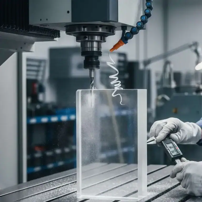
How To Measure Surface Roughness?
Surface roughness should be measured with a method that matches the part geometry, required parameter, and inspection purpose. Contact and non-contact methods each have different strengths, so the choice of measurement approach directly affects result accuracy and reliability.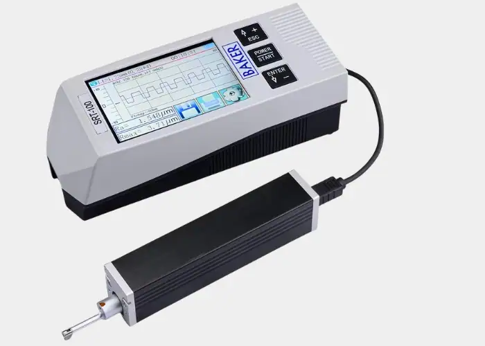
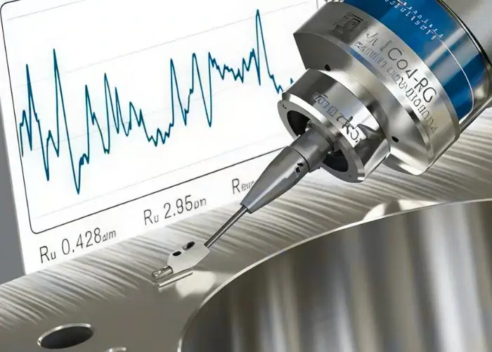
1.Contact Profilometer
A contact profilometer uses a stylus to trace the surface and record the profile. It is one of the most widely used tools for measuring Ra, Rz, and similar parameters. This method works well for many machined parts, but stylus access, travel direction, and tip size still need to match the feature being measured.
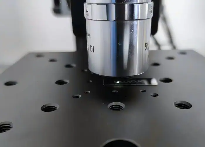
2.Non-Contact Measurement Methods
Non-contact systems use optical, laser, or other sensor-based technologies to measure the surface without physical contact. These methods are useful for delicate or easily damaged surfaces. They can provide fast and detailed analysis, but setup, calibration, and surface reflectivity must be controlled carefully to get reliable data.
3.Portable Surface Roughness Tester
A portable tester is useful for quick checks on the shop floor or at incoming inspection. It allows roughness values to be verified without moving the part to a full metrology station. This makes it practical for process monitoring, but the instrument still needs to match the accuracy and parameter requirement on the drawing.
4.Surface Finish Comparator
A surface finish comparator is a sample reference block used to compare surface texture visually or by touch. It is quick and convenient for rough in-process checks. However, it is not a substitute for instrument-based measurement when tighter finish values or formal inspection records are required.
5.Choosing The Right Measurement Method
The right method depends on the part size, surface accessibility, roughness parameter, required accuracy, and whether the measurement is for process control or final inspection. For tight functional requirements, a more controlled method is usually preferred. For general shop checks, faster portable methods may be enough.
Machining Surface Roughness By Process
Different machining processes naturally produce different surface finish levels, so roughness should always be reviewed together with the process used to make the part. Turning, milling, grinding, and EDM each create different textures, capabilities, and finish expectations.
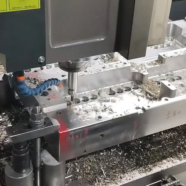
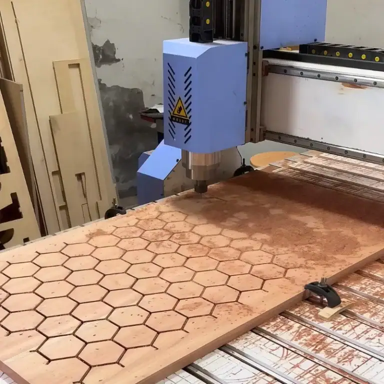
1.Milling Surface Finish
Milling often leaves a visible cutter path on the surface. Finish depends on cutter condition, path strategy, feed per tooth, and machine rigidity. Flat faces and contoured surfaces may show different textures, especially if chatter or deflection is present during cutting.
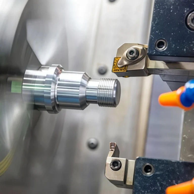
2.Turning Surface Finish
Turning often creates a regular surface pattern along cylindrical features. Its finish is strongly influenced by feed rate, insert geometry, tool wear, and machine stability. Fine turning can achieve good finish levels when the setup is rigid and the cutting parameters are well controlled.
3.Grinding Surface Finish
Grinding is widely used when a part needs both fine finish and dimensional accuracy. It is often selected for hardened materials, sealing areas, and precision contact surfaces. Grinding is slower and more specialized than general machining, but it can deliver very consistent finish when the application requires it.
EDM And Other Special Processes
EDM and similar processes can create detailed features and hard-material geometries, but surface finish depends heavily on process settings and finishing passes. These surfaces often need special review because the finish may not be suitable for the final function without additional processing.
Machining Surface Roughness Chart By Process
| Process | Typical Finish Range | Notes |
| Milling | Medium to rough/fine | Depends on path, rigidity, and tool wear |
| Turning | Fine to medium | Affected by feed and insert geometry |
| Grinding | Very fine to fine | Strong finish and dimensional control |
| EDM | Variable | Depends on settings and skim passes |
Factors That Affect Surface Roughness In Machining
Surface roughness in CNC machining is not controlled by one setting alone, because the final finish depends on the entire cutting system. Speed, feed, tooling, material behavior, machine stability, and coolant all work together to influence the surface result.
1. Cutting Speed
Cutting speed influences heat generation, chip formation, and the way the cutting edge interacts with the workpiece material. If the speed is too low, the cut may become unstable and built-up edge may appear more easily. If the speed is too high, excessive heat can damage the tool edge and reduce the consistency of the finished surface.
The correct speed range helps improve finish quality by supporting smoother cutting action and more stable chip flow. In CNC machining, cutting speed should always be selected together with material type, tool condition, and process goal rather than treated as an isolated setting.
2. Feed Rate
Feed rate is one of the strongest variables affecting surface roughness because it directly changes the spacing and depth of the tool marks left on the part. In general, a higher feed rate creates a rougher surface, while a lower feed rate produces a finer and more uniform finish.
However, feed rate should be optimized rather than simply reduced. If the feed is too low, productivity drops and cutting action may become less efficient in some materials. The best result usually comes from balancing finish quality, machining time, chip load, and tool behavior together.
3. Tool Geometry And Tool Wear
Tool geometry has a major influence on the final surface condition. Nose radius, rake angle, edge sharpness, and insert design all affect how the tool cuts the material and what kind of texture is left behind. A tool with more suitable geometry can often improve finish without changing the machine or the material.
Tool wear is equally important. As the cutting edge becomes worn, chipped, or unstable, the surface finish can deteriorate quickly. For this reason, finish-critical operations usually require not only the correct tool geometry, but also a stable tool condition during the final pass.
4. Workpiece Material
Different materials respond differently under the same cutting conditions, which means the same program will not always produce the same finish quality across different alloys. Aluminum, stainless steel, titanium, and cast iron each have different hardness, ductility, thermal behavior, and chip formation characteristics.
These differences affect how smoothly the tool cuts, how heat builds up, and how the surface is formed. When setting surface finish expectations, material behavior should always be considered together with tooling, cutting data, and the required part function.
5. Machine Stability And Setup
Machine stability and setup quality have a direct effect on roughness consistency. Even with correct cutting parameters, poor rigidity in the spindle, fixture, workholding, or tool extension can create chatter, vibration, and irregular tool marks on the finished surface.
In many real machining problems, poor finish is caused less by the programmed values and more by mechanical instability in the setup. A rigid machine, secure clamping, and well-supported part geometry are often necessary to maintain reliable surface quality from one part to the next.
6. Coolant And Lubrication
Coolant and lubrication help control heat, reduce friction, and improve chip evacuation during machining. In many cases, they also improve surface finish by reducing material smearing, lowering tool wear, and keeping the cutting action more stable.
Poor lubrication can lead to built-up edge, dragging, local tearing, and inconsistent texture, even when the cutting speed and feed rate look reasonable. That is why coolant strategy should be matched to the material, tooling, and finish requirement rather than treated as a secondary detail.
How To Choose The Right Surface Finish For Your Part?
Choosing the right surface finish for a part should be based on how the part will function in real use, which surfaces are truly critical, and whether the required finish improves sealing, wear, fit, motion, or appearance. A practical decision should also consider machining capability, inspection effort, material behavior, and total production cost, so the final requirement is functional, manufacturable, and cost-effective.
1.Functional Surfaces
Functional surfaces should usually be reviewed first because they directly affect how the part performs in service. If a surface controls sealing, motion, contact, wear, or load transfer, its roughness requirement should be chosen according to that function rather than by default.
In practice, these surfaces often justify tighter finish control because poor texture can reduce performance even when the dimensions are correct. The key decision is whether the finish changes how the part works, not simply how the surface looks.
2.Cosmetic Surfaces
Cosmetic surfaces should be specified according to visible quality expectations, customer requirements, and the final appearance standard of the product. These surfaces may need a cleaner and more uniform finish, but they do not always require the same precision level as functional areas.
The decision should be based on what the customer will actually see and how the surface will appear after coating, anodizing, plating, or polishing. In many cases, appearance can be improved without applying unnecessarily tight machining roughness values.
3.Sealing And Sliding Surfaces
Sealing and sliding surfaces usually require more careful finish selection because roughness directly affects leakage, friction, wear, and long-term surface behavior. These areas often need smoother and more stable finishes than surrounding non-critical faces.
The decision should consider the working condition of the part, such as fluid sealing, repeated motion, contact load, or lubrication. If surface roughness can influence performance over time, this area should be treated as a priority during specification.
4.Tight-Tolerance Features
Tight-tolerance features should be reviewed together with surface finish because dimensional accuracy alone may not guarantee good assembly performance. A part can meet size limits but still perform poorly if the surface condition interferes with fit, alignment, or contact behavior.
For this reason, precision bores, datum faces, locating steps, and other tolerance-sensitive features often need finish requirements that match their assembly or positioning role. The decision should be based on function, not only on drawing habit.
5.Balancing Surface Finish, Cost, And Manufacturability
The best finish decision is usually the one that gives enough surface quality to meet the real requirement without adding unnecessary machining difficulty or inspection cost. Lower Ra values often look safer on paper, but they can increase cycle time, tooling demand, and production expense.
A better engineering decision comes from separating critical surfaces from non-critical ones and applying tighter control only where it creates real value. This approach helps keep the part functional, manufacturable, and cost-effective at the same time.
Surface Roughness Examples In Real Applications
Surface roughness becomes easier to specify when it is connected to real parts, real functions, and actual engineering use cases rather than treated only as a number in a chart. Looking at practical examples helps engineers and buyers understand how roughness values are used in production.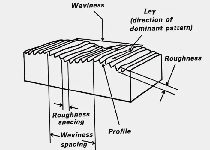
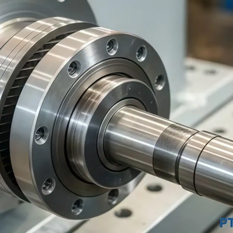
Surface Roughness In CNC Machined Housings
For CNC machined housings, Ra 3.2 is commonly used as the standard surface roughness for general surfaces. However, sealing faces and locating surfaces often require a finer finish to ensure proper assembly, accurate positioning, and reliable sealing performance. As a result, one housing part may include different surface finish requirements in different areas.
Surface Finish Changes After Secondary Processing
Molded, plated, anodized, or coated parts may begin with one surface condition and end with another after later processing. For this reason, final finish should always be reviewed in the delivered condition rather than only in the machined state.
Material-Based Surface Finish Differences
Stainless steel, aluminum, and precision components often require different finish strategies because their material behavior, application needs, and process response are different. The same finish value may not create the same practical result across different materials.
Common Roughness Values In Real Part Design
In many practical designs, a general machined surface may allow Ra 3.2, while a sealing face or contact area may require Ra 0.8 or finer. This difference shows why roughness should be tied to function instead of applied uniformly across the whole part.
Common Surface Roughness Questions In Manufacturing
In real manufacturing work, surface roughness questions often appear when teams are balancing finish quality, machining capability, production cost, and drawing requirements at the same time. These issues usually come up during quoting, process planning, inspection, and customer communication, and many of them can be reduced when roughness requirements are reviewed earlier from both engineering and manufacturing perspectives.
Surface Roughness Cost Impact
One of the most common manufacturing questions is how surface roughness influences cost. In practice, finer finishes often require slower feed rates, more stable setups, better tooling, and sometimes additional finishing operations such as grinding, polishing, or fine passes.
Because of this, a tighter roughness requirement can quickly increase machining time, inspection effort, and tool wear. That is why roughness should be specified according to function, not simply chosen as the lowest possible value.
Lower Ra And Surface Finish Performance
Another frequent question is whether a lower Ra value always means a better part. The answer is no. A smoother surface may improve sealing, appearance, or sliding performance, but only when those functions actually matter in service.
If the lower value does not improve part performance, the added requirement may only raise cost without creating real engineering value. In manufacturing, the best surface finish is usually the one that is good enough for the function, not the one that is simply the finest.
Secondary Finishing Effects On Surface Condition
Teams also often ask whether anodizing, plating, blasting, coating, or polishing will change the final surface condition. In most cases, the answer is yes. Secondary finishing can change texture, gloss, contact behavior, and the measured roughness value of the delivered part.
For that reason, roughness should be reviewed in both the machined state and the final delivered state whenever the drawing or application requires it. A finish that looks acceptable before treatment may not remain the same after the full process route is complete.
Parameter, Unit, And Reference Tool Confusion
A further common problem is confusion between roughness parameters, units, and comparison tools. Teams may mix Ra with Rz, confuse micrometers with microinches, or rely on conversion tables without first confirming which parameter the drawing actually requires.
Conversion charts and calculators are useful, but only when the specification is already clear. Before using any reference tool, the required parameter, value, unit, and inspection method should all be confirmed to avoid quoting errors, process mismatch, or inspection disputes.
Early Engineering Review In Surface Finish Planning
Many of these questions become problems only because they are discussed too late. If roughness requirements are reviewed early, teams can check whether the value matches part function, whether the process can achieve it efficiently, and whether the drawing is calling out the right parameter.
This kind of review helps reduce rework, avoid unnecessary finish requirements, and improve communication between engineering, production, and suppliers. In real projects, early alignment usually saves more cost than trying to correct roughness decisions after machining has already started.
FAQs
What Is The Difference Between Ra And Rz?
Ra shows the average surface roughness, while Rz focuses on peak-to-valley variation. Because of this, Rz is often more sensitive to local surface extremes than Ra. Two surfaces may have the same Ra but still show different Rz values. That is why the correct parameter depends on the actual function of the part.
How Is Surface Roughness Usually Measured?
Surface roughness is usually measured with a profilometer, tester, comparator, or optical method. The right method depends on part geometry, required parameter, and inspection purpose. Contact methods are common for machined parts and standard roughness evaluation. Non-contact methods are useful for delicate, soft, or highly detailed surfaces.
What Is A Typical Ra Value For Machined Parts?
A typical machined surface often falls around Ra 1.6 to Ra 3.2, depending on the process. Finer finishes such as Ra 0.8 or below are common on critical sealing or contact areas. Rougher values may still be acceptable on non-critical or general engineering surfaces. The right target depends on function, tolerance, material, and cost expectations.
Why Is A Surface Roughness Chart Useful?
A surface roughness chart helps compare finish levels, units, symbols, and roughness values. It makes it easier to connect drawing callouts with process capability and inspection needs. Engineers and buyers can use it to avoid over-specifying or misreading finish requirements. It is a practical tool for balancing function, manufacturability, and production cost.
Conclusion
A surface roughness chart is an essential reference in machining and manufacturing because it helps engineers, buyers, and production teams compare finish values, understand roughness parameters, and make better decisions on measurement and specification. Knowing how to read symbols, evaluate Ra and Rz values, and match finish requirements to part function helps reduce cost and improve machining quality.
At TiRapid, we provide reliable CNC machining and custom manufacturing support for high-quality parts. Send us your drawings or CAD files to get the right surface finish solution for your project.