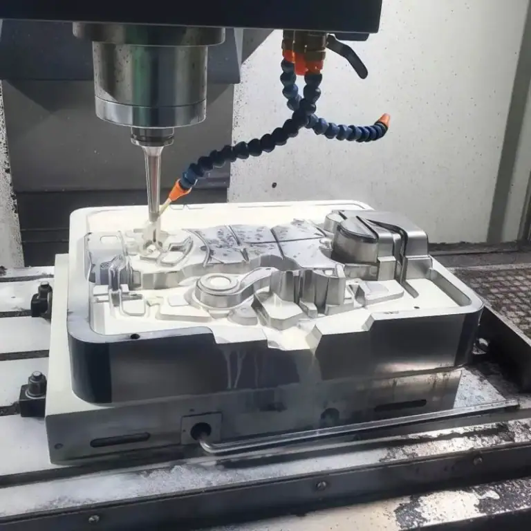
Shoulder milling creates flat surfaces and precise 90° shoulders in one pass. Widely used in mold, automotive, aerospace, and medical machining, it’s essential for steps, slots, and cavity edges. In this article, I will introduce you to its core technologies—tool selection, process planning, parameters, quality control, and solutions—to help you master this demanding yet crucial machining method.
What Is Shoulder Milling
Shoulder milling produces precise right-angle shoulders perpendicular to an existing surface, usually with angle error within ±0.02 mm and smooth, burr-free transitions. Its main advantage is achieving flat and vertical surfaces in a single pass, reducing setups and cumulative errors. In my work, I often machine 90° ±0.01° shoulders on aluminum or steel, a common requirement in automotive, aerospace, and mold components.
How To Determine The 90° Right-Angle Shoulder
The accuracy of the 90° shoulder is typically assessed using Coordinate Measuring Machines (CMMs), capable of detecting perpendicularity errors within a range of ±0.005–0.01 mm per 100 mm. For less critical applications, precision angle gauges or dial test indicators mounted on reference squares may be sufficient, but these lack the repeatability of CMM verification.
Tolerance Standards: In automotive and aerospace, perpendicularity tolerances are often set at 0.01–0.02 mm/100 mm, while in general machining they may be relaxed to 0.05 mm per 100 mm.
Surface Transition: Beyond dimensional accuracy, the transition between the shoulder and the base surface must be burr-free and smooth, as residual burrs or scallops can compromise sealing surfaces or lead to premature wear.
What Are The Applicable Scenarios For Shoulder Milling
| Industry / Field | Application Scenario | Typical Machined Features |
| Mold Making | Vertical machining of cavity edges and bottoms | Cavity shoulders, bottom surfaces |
| Aerospace | Structural ribs and cavity steps in components | Frame ribs, fuselage steps |
| Automotive | Precision shoulder machining of engine and housing parts | Cylinder head surfaces, gearbox housings |
| Medical Devices | High-accuracy shoulders in implants and brackets | Orthopedic implants, support plates |
| Precision Machinery | Guide rails and slots requiring tight tolerances | Linear guide shoulders, locating grooves |
| Electronics & Semiconductor | Heat sinks and housing steps | Cooling fins, chip packaging shoulders |
| Energy Equipment | Critical shoulders in pumps and turbines | Blade roots, flow channel shoulders |
| Robotics & Automation | Lightweight aluminum frames and rail shoulders | Robot joints, guide rail slots |
What Are The Types Of Tools For Shoulder Milling
Shoulder milling relies on diverse tools: square shoulder cutters for 90° surfaces, end mills for small parts, long edge cutters for deep cavities, indexable cutters for cost-efficient volume work, solid carbide tools for high precision, and side & face cutters for combined milling.Understanding the various types of tools will help you choose the right tool for your production.
Types Of Shoulder Milling Tool
Square Shoulder Cutter
Square shoulder cutters are designed with a standard 90° entry angle, enabling simultaneous machining of flat surfaces and perpendicular walls in a single pass. They are best suited for medium and shallow cuts, reducing setup errors. For example, in mold manufacturing, they are widely used to process cavity edges and bottom faces, ensuring smooth transitions without the need for secondary finishing.
End Mill
End mills, with their smaller diameters, are ideal for accessing tight spaces and performing localized machining on small parts. They provide high precision and are especially valuable in medical device manufacturing. For instance, I often use them for guide grooves or miniature step features where ±0.01 mm shoulder accuracy is required.
Long Edge Milling Cutter
Long edge milling cutters feature extended cutting edges, making them highly efficient for deep cavity and groove machining by minimizing the number of step-down passes. In aerospace applications, they are commonly used to machine stiffeners and deep structural pockets, maintaining perpendicularity tolerances within 0.02 mm per 100 mm.
Indexable Cutter
Indexable cutters allow insert replacement while reusing the tool body, offering a cost-effective solution for high-volume production. The versatility of insert grades and coatings enables machining of a wide range of materials. In automotive production lines, they are frequently applied to mass-produce aluminum engine blocks, balancing both productivity and economy.
Solid Carbide Tool
Solid carbide tools deliver superior hardness, rigidity, and wear resistance, making them the preferred choice for high-precision finishing. They excel in operations requiring tight tolerances. In mold cavity machining, for example, I rely on solid carbide shoulder mills to achieve shoulder angle precision of ±0.01°, eliminating the need for post-grinding.
Side & Face Cutter
Side and face cutters can machine both the side and bottom surfaces simultaneously, significantly improving process efficiency. They are highly suitable for combined milling tasks. In precision mechanical components such as linear guide rails, I often use them to finish shoulders and bottom faces in one setup, reducing clamping errors and improving consistency.
Tool Holding Methods
| Tool Holding Method | Runout Accuracy | Advantages | Typical Applications |
| Heat-Shrink Holder | Radial runout <0.003 mm | Excellent rigidity, maintains perpendicularity within ±0.01°/100 mm | Aerospace structural parts, precision mold shoulders |
| Hydraulic Holder | Radial runout <0.005 mm | Damping effect, extends tool life by 15–20%, surface roughness up to Ra 0.4 μm | Finishing of aluminum alloys and hardened steels |
| High-Power Collet Chuck | Radial runout <0.01 mm | High torque, suitable for radial depths of cut up to 0.5×D | Roughing of automotive engine blocks, mold bases |
| Pull Stud Accuracy Control | Concentricity error <0.01 mm | Prevents shoulder angle deviation, requires periodic calibration | Universal use in all high-precision shoulder milling scenarios |
What are the process steps of shoulder milling
The goal of square shoulder milling is to obtain both a flat surface and a vertical wall in a single pass, forming a precise 90° shoulder. This process is widely applied in industries such as aerospace, automotive mold manufacturing, and precision machinery. A mature workflow typically includes process planning, tool selection, tool clamping, machining strategy, cooling & chip evacuation, and precision inspection.
Process Planning
In the process design stage, the machining strategy should be determined based on the geometry, shoulder depth, wall thickness, and material properties of the part.
Shallow Shoulder Milling (≤2×D cutting depth)
Can usually be completed in a single cut, improving efficiency by 30%–40%, ideal for mass production.
Deep Shoulder Milling (>2×D cutting depth)
Requires a step-down strategy, with a maximum depth of cut not exceeding 70% of the tool’s cutting edge length. For example, with a cutting edge length of 20 mm, the recommended depth per pass should not exceed 14 mm.
Thin-Wall Shoulders (Height-to-thickness ratio >15:1)
Such parts are prone to vibration and deformation. Techniques like waterline milling, step supports, or vibration-damping tool holders can reduce deformation by 20–35%.
Tool Selection
The tool geometry and performance are the primary factors determining accuracy and surface quality.
Square Shoulder Cutters
Feature a standard 90° entering angle, suitable for conventional shoulder milling.
Long Edge Cutters
Cutting edge length can be 4–6 times the tool diameter, suitable for deep cavities and tall walls.
Solid Carbide Tools
Provide very high accuracy with shoulder angle tolerance of ±0.01°, often used in mold and precision component machining.
Indexable Cutters
Suitable for high-volume production. Tool inserts are cost-efficient, reducing per-part tooling cost by 20–50% compared to solid tools.
Tool Clamping
Tool clamping rigidity and runout directly affect shoulder accuracy.
Shrink-fit Tool Holders: Radial runout <0.003 mm, ideal for high-precision machining.
Hydraulic Chucks: Suitable for finishing operations, ensuring stable clamping.
High-Power Collet Chucks: Recommended for roughing, ensuring safety under heavy cutting loads.
Additionally, the pull stud concentricity should be calibrated regularly, with clamping error not exceeding 0.005 mm.
Machining Strategy and Entry Methods
The tool entry method depends on the part structure:
Rolling-in Entry
Tool follows an arc trajectory into the material, reducing instantaneous impact force by 25–30%.
Ramp-in Entry
Tool enters at an angle of 3°–7°, suitable for deep grooves and long-edge cutters, extending tool life by 15–20%.
Cooling and Chip Evacuation
Cooling and chip evacuation strongly influence tool life and surface finish:
Dry Cutting: Best for cast iron, avoids thermal cracking.
Wet Cutting: Recommended for steels, extending tool life by 1.5×.
Internal High-Pressure Coolant (50–70 bar): Ideal for titanium alloys and stainless steels, improving chip evacuation and reducing chipping rate by 40%.
MQL (Minimum Quantity Lubrication): Recommended for aluminum alloys, extending tool life by 20–30% with added environmental benefits.
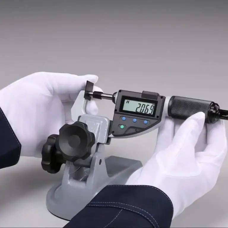
Precision Inspection and Quality Control
Shoulder accuracy and squareness must be verified with strict inspection methods:
CMM (Coordinate Measuring Machine): Measures squareness with an accuracy of 0.01 mm/100 mm.
Angle Gauges or Go and No-Go Gauges: Provide quick in-process checks, useful in mass production.
For high-precision parts, a finishing allowance of 0.2–0.3 mm is typically left, and final accuracy is achieved through a light finishing cut.
How To Select The Right Cutting Parameters
In square shoulder milling, the choice of cutting parameters directly affects shoulder squareness, surface quality, and tool life. Incorrect parameters may lead to issues such as tool chipping, step marks, vibration, and overcutting. Therefore, optimization must be carried out according to machining objectives, workpiece material, and machine rigidity.
Spindle Speed And Feed Rate
Spindle Speed (n)
Calculation formula:
where Vc = cutting speed, D = tool diameter.
Typical cutting speed ranges in square shoulder milling:
Aluminum: 400–800 m/min
Steel: 150–250 m/min
Cast Iron: 100–200 m/min
Heat-Resistant Alloys: 40–80 m/min
Feed Rate (Vf)
Formula:
Vf=n×z×fz
where z = number of teeth, fz = feed per tooth.
Feed per Tooth And Width And Depth Of Cut Matching
Feed per Tooth (fz)
Determines cutting thickness and surface finish:
Aluminum: 0.05–0.20 mm/tooth
Steel: 0.03–0.12 mm/tooth
Cast Iron: 0.05–0.15 mm/tooth
Heat-Resistant Alloys: 0.02–0.08 mm/tooth
Width of Cut (ae) and Depth of Cut (ap)
Roughing: ae = 50–80% of tool diameter, ap = 0.5–1.5×D
Finishing: ae = 5–15% of tool diameter, ap = 0.1–0.3 mm
In shoulder milling, a large radial width and small axial depth are often preferred to keep the shoulder angle stable within ±0.01°.
Differentiated Parameters For Aluminum, Steel, Cast Iron, And Heat-Resistant Alloys
| Material | Cutting Speed & Feed | Cooling Method | Key Notes |
| Aluminum Alloys | High spindle speeds 600–800 m/min, with large feeds | MQL or cold air cooling, extends tool life 20–30% | Low cutting forces, tool life mainly depends on chip evacuation & built-up edge control |
| Steel | Cutting speed 150–250 m/min, moderate feed per tooth 0.05–0.10 mm/tooth | Wet cutting preferred, extends tool life 1.5× | Balanced cutting strategy to control heat concentration |
| Cast Iron | Cutting speed 100–200 m/min, larger feed per tooth 0.08–0.15 mm/tooth | Dry cutting recommended | Prevents thermal cracking, high productivity possible |
| Heat-Resistant Alloys (Titanium, Nickel-Based) | Low cutting speeds 40–80 m/min, small feed 0.02–0.06 mm/tooth | High-pressure internal coolant (50–70 bar) | Tools wear quickly, step-down strategy recommended, depth ≤70% of cutting edge length |
Vibration And Step Mark Control: Unequal Pitch, Variable Helix, Phase Shift
Unequal Pitch Design
Cutting edges with unequal spacing disrupt vibration frequency, reducing chatter amplitude by 20–30%.
Variable Helix
Different helix angles distribute cutting forces more evenly, improving surface finish.
In square shoulder milling, surface roughness can be improved from Ra 3.2 μm to Ra 1.6 μm.
Phase Shift
Axial or circumferential displacement of cutting edges prevents all teeth from engaging simultaneously, reducing step mark depth by 40%.
Process Optimization
Using ramp-in entry (3°–7°) with high-rigidity tool holders significantly reduces vibration and step patterns.
Quality And Accuracy Control
By combining precise inspection methods with data-driven compensation strategies, square shoulder milling ensures not only dimensional tolerance but also superior surface transition and flatness control. Especially for thin-walled parts, the integration of prediction and closed-loop correction allows me to consistently achieve high precision and stable machining quality.
Key Inspection Points
90° Angle: Verified using a Coordinate Measuring Machine (CMM) or precision angle gauges, ensuring the shoulder angle remains within ±0.01°.
Flatness: Required to be within 0.01 mm/100 mm, ensuring stable and reliable reference surfaces.
Step Transition: By optimizing tool paths and leaving a small finishing allowance, the transition areas are free from noticeable tool marks or step differences, resulting in superior surface quality.
Thin-Wall Deformation Control
Prediction and Compensation: For thin-walled components with a height-to-thickness ratio greater than 15:1, I analyze cutting force directions in advance to predict possible elastic deformation and apply reverse compensation in the tool path.
On-Machine Measurement and Closed-Loop Correction: Using touch probes or laser measuring systems, I conduct real-time inspection during machining and feed measurement results back to the CNC system. This enables closed-loop correction, effectively minimizing wall deflection and maintaining dimensional errors within ±0.02 mm.
Cooling And Lubrication In Machining
The cooling method directly affects tool life and surface quality. Common cooling methods used in shoulder milling include dry cutting, wet cutting, MQL (minimum quantity lubrication), and Internal Coolant Supply.By flexibly selecting the cooling strategy, I can achieve the best machining results based on material properties, cutting depth, tool geometry and machine rigidity.
Cooling Strategies
Dry Cutting
I typically use dry cutting when machining gray cast iron and ductile cast iron, as these brittle materials generate segmented chips and do not retain excessive heat.
Dry cutting helps prevent thermal cracking caused by cutting fluids and reduces coolant consumption costs.
With optimized cutting parameters, I can consistently maintain dimensional accuracy within ±0.02 mm for cast iron parts.
Wet Cutting
For steel and aluminum alloys, which generate higher cutting temperatures, I prefer wet cutting.
Using emulsions or water-soluble coolants creates a protective cooling film between tool and workpiece, effectively reducing tool wear.
Under wet cutting conditions, tool life can be extended by 1.5 times or more, while surface roughness is reduced by approximately 20%.
MQL (Minimum Quantity Lubrication)
In environmentally focused and high-efficiency applications, I use MQL, with flow rates typically controlled between 50–150 ml/h.
For aluminum machining, MQL significantly reduces built-up edge formation and increases tool life by 20–30%.
Compared with conventional wet cutting, MQL not only minimizes coolant usage but also lowers waste fluid treatment costs by around 40%.
Internal Coolant Supply
For deep cavities, slots, or heat-resistant alloys such as titanium and nickel-based alloys, I prioritize high-pressure internal coolant systems, usually operating at 50–70 bar.
High-pressure coolant directly reaches the cutting edge and chip separation zone, greatly improving chip evacuation and preventing tool chipping caused by chip accumulation.
With internal cooling, I can effectively control cutting temperatures, extend tool life by 30–40%, and maintain dimensional tolerances within ±0.01–0.02 mm.
Key Points In Square Shoulder Milling
During square shoulder milling, I strictly follow an “application checklist” to ensure that every step—including process planning, tool path design, and workpiece fixturing—meets the requirements of stability, controllability, and high precision. By adopting this approach, it is possible to maintain dimensional accuracy within ±0.01–0.02 mm in mass production and keep surface roughness consistently within the range of Ra 0.6–0.8 μm.
Application Checklist
Shallow, Deep, And Local Shoulders
Shallow shoulder milling (cutting depth ≤2×D): Can typically be completed in a single pass, reducing machining time by over 30%.
Deep shoulder milling (cutting depth >2×D): Requires a step-down approach, with each depth limited to ≤70% of cutting edge length, combined with high-pressure internal cooling to avoid tool overload or chipping.
Local shoulders: Best addressed with smaller-diameter tools in secondary passes, ensuring shoulder angle accuracy within ±0.01° and avoiding overcutting.
Optimization of Side and Face Milling Sequences
A common sequence is side milling first, followed by face milling, which helps reduce concentrated cutting forces and minimize workpiece deformation.
For large-surface machining, a roughing-to-finishing strategy is applied: roughing with radial engagement of 50–80% of tool diameter, finishing with 5–15% engagement.
Optimized sequencing has been shown to shorten machining cycle times by up to 25% and reduce step transition defects to below 3%.
Workpiece Fixturing and Vibration Reduction
For standard parts, back support + side clamping provides stable three-directional positioning.
In high-precision operations, custom fixtures are recommended, allowing clamping error to be controlled within 0.01 mm.
For thin-walled components, the addition of damping blocks or filler materials can reduce wall vibration amplitude by 20–40%.
Regular inspection of fixture locating pins and pull studs helps prevent accumulated errors from fixture wear.
Common Problems And Solutions In Practical Machining
By systematically addressing issues such as burr formation, step accuracy, tool chipping, chatter, and thin-wall deformation, machining consistency and product yield can be significantly improved. These corrective measures not only ensure reliable workpiece quality but also deliver measurable gains in overall productivity and tool cost efficiency.
Common Problems And Countermeasures
Burr Formation
Typical Symptom: Burrs appear along the shoulder or exit edges, affecting assembly accuracy and post-processing.
Solution: Increase cutting speed (Vc +10–20%) to ensure a cleaner cut and replace inserts with sharper edges (recommended 0.02–0.04 mm edge chamfer). With this adjustment, burr height can be controlled within ≤0.05 mm.
Step Deviation (Non-Straight Steps)
Typical Symptom: Shoulder steps appear tilted or wavy, leading to squareness errors.
Solution: Inspect radial runout, ensuring it is ≤0.003 mm, use high-precision shrink-fit or hydraulic chucks to enhance rigidity and stability. These measures keep step straightness errors within 0.01 mm/100 mm.
Tool Chipping
Typical Symptom: Cutting edges break prematurely, resulting in poor surface finish.
Solution: Reduce feed per tooth (fz −10–15%) to decrease cutting load, use coated tools with stronger wear resistance such as TiAlN or AlCrN coatings. This approach extends tool life by 30–50%.
Chatter and Vibration
Typical Symptom: Vibration marks appear on the machined surface, often accompanied by loud noise and early tool failure.
Solution: Reduce tool overhang (recommended ≤5× tool diameter) to minimize vibration amplitude, adopt anti-vibration tool holders for high-precision finishing. With these measures, surface roughness can be improved from Ra 3.2 μm to Ra 1.6 μm.
Thin-Wall Springback and Deformation
Typical Symptom: Thin-walled parts with high aspect ratios exhibit wall deflection or springback after machining, causing dimensional errors.
Solution: Predict cutting force direction in CAM simulation and apply reverse compensation of 0.02–0.05 mm, integrate on-machine probing (touch probe or laser scanning) for closed-loop correction. These methods stabilize dimensional accuracy within ±0.02 mm.
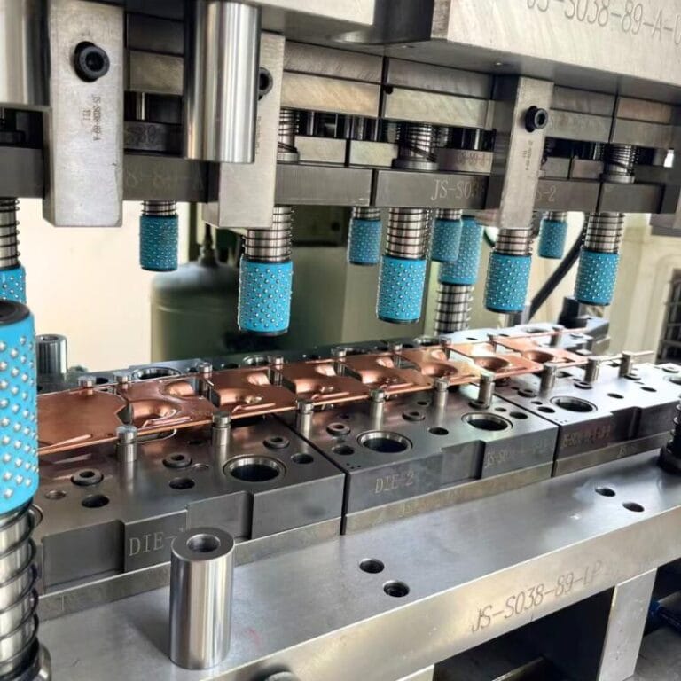
Production Line Considerations
In mass production, square shoulder milling is not only a cutting process but also a systematic approach that must balance cost, efficiency, safety, and maintenance. Focusing solely on machining accuracy without addressing production line factors often leads to higher costs or reduced throughput. The following aspects are critical in achieving stable and sustainable production performance.

Cost And Efficiency
Tool Life and Tool Change Cycles
Tool life directly affects per-part cost in large-scale production. For example, if one tool can machine 200 parts, but by optimizing cutting parameters or selecting an advanced coating it can reach 260 parts, the tool cost per part is reduced by approximately 23%.
Additionally, tool change downtime—including stopping the machine, resetting, and recalibration—can account for 10–15% of the production cycle time. By improving tool life and optimizing tool change intervals, downtime can be reduced by 20–30%, resulting in an overall production efficiency gain of 8–12%.
Single-Clamping Completion Rate
Completing multiple milling operations in a single setup minimizes positioning errors and boosts output. Studies from production data show that increasing the single-clamping completion rate from 70% to 90% can reduce cycle times by 15% and lower scrap rates by more than 10%.
Safety
Chip Flow Management
High-speed milling of aluminum and steel generates long, continuous chips. Poor chip evacuation can cause re-cutting, tool breakage, or flying debris. Installing high-pressure chip evacuation systems and optimizing chip flow direction reduce tool breakage by 15–20% while improving operator safety.
Thin-Wall Clamping Force Control
Thin-walled components are prone to clamping deformation. By applying low-pressure hydraulic clamping combined with damping support blocks, deformation can be reduced from 0.05–0.08 mm to 0.02–0.03 mm, significantly improving part quality.
Maintenance
Cutter Body Runout Calibration
Axial and radial runout of the cutter body can lead to uneven cutting loads and poor squareness. Regular calibration using dial indicators or laser interferometers ensures cutter runout stays within ≤0.005 mm. This practice extends tool life by up to 20% while maintaining stable dimensional accuracy.
Insert Seat and Toolholder Care
Contaminants or chips in insert seats can cause misalignment. Cleaning insert pockets during each tool change, along with regular anti-rust and lubrication treatments for toolholders, reduces tool rejection rates by approximately 15% and ensures better machining consistency after tool replacement.
Advanced Topics in Shoulder Milling
Advanced shoulder milling integrates 5-axis machining, high-speed strategies, and advanced tooling to boost accuracy and productivity. Single-setup machining reduces errors by 50%, while HSM/HFM raise efficiency by up to 200%. CVD, PCD, and PCBN tools extend tool life 2–5 times. Surface texture engineering further improves wear resistance and functional properties, making the process essential in aerospace, automotive, and precision mold manufacturing.
5-Axis and Swiveling Head Shoulder Milling
In complex part manufacturing, the use of 5-axis machining or swiveling head milling enables multi-face shoulder machining in a single setup, minimizing cumulative error. Compared with traditional 3-axis methods, 5-axis shoulder milling reduces positioning error by 30%–50% and significantly improves consistency in complex cavities and freeform surfaces. For aerospace structural components, 5-axis shoulder milling allows deep cavity, step, and thin-wall areas to be processed in one operation, reducing risks associated with secondary clamping.
High-Speed and High-Feed Shoulder Milling Strategies
High-speed machining (HSM) and high-feed milling (HFM) are key strategies for improving efficiency:
HSM: Commonly applied in aluminum alloys with cutting speeds of 600–1200 m/min and feed per tooth of 0.05–0.15 mm/tooth. This reduces cutting forces and heat generation, extending tool life by 20%–40%.
HFM: Particularly effective for soft steels and mold steels, with feed per tooth increased to 0.5–1.5 mm/tooth. Although depth of cut is shallower (ap 0.5–1.0 mm), the metal removal rate (MRR) can increase by more than 200%, making it ideal for roughing large volumes efficiently.
Tool Materials And Coatings
Tool performance is heavily influenced by substrate and coating selection:
CVD-Coated Carbide: Suited for steels and cast iron, offering superior wear resistance. Tool life is 1.5–2 times longer than PVD coatings in continuous cutting.
PCD (Polycrystalline Diamond): Recommended for aluminum alloys and composites, supporting cutting speeds up to 2000 m/min while achieving surface roughness as low as Ra 0.6–0.8 μm.
PCBN (Polycrystalline Cubic Boron Nitride): Ideal for heat-resistant alloys and hardened steels above 55 HRC. Tool life is extended by 3–5 times compared to carbide, especially under stable cutting conditions.
Surface Texture Engineering
Modern shoulder milling extends beyond dimensional accuracy to functional surface engineering. By optimizing tool paths (e.g., radial spiral or alternating trajectories), micro-textures can be intentionally generated:
Tribological Enhancement: Surface textures reduce the coefficient of friction by 10%–15%, improving wear resistance in hydraulic components and sliding pairs.
Coating Adhesion: Optimized roughness and surface orientation increase coating or plating bond strength by 20%–30%.
Optical and Fluid Applications: Specific surface waveforms generated by milling paths can enhance light scattering or improve microfluidic flow efficiency.
FAQs
Is Shoulder Milling Safe?
Yes, I consider shoulder milling safe when the correct parameters are applied. By controlling radial runout to within 0.005 mm, using rigid toolholders, and ensuring chip evacuation, the risk of tool breakage is minimized. With high-pressure coolant (50–70 bar), thermal cracks are reduced by 40%. Proper fixturing and guarding also protect operators from flying chips, making the process safe for both production and high-precision machining.
Is Shoulder Milling Expensive?
Shoulder milling is not inherently expensive, but costs depend on tool life and cycle time. For instance, carbide inserts in steel can last around 45–60 minutes of cutting, translating to $0.20–0.30 per component in mass production. Toolholders and precision fixturing increase upfront costs, but efficiency gains offset this. By optimizing feeds and speeds, I often reduce per-part costs by 15–20% compared to conventional milling.
What’s the Difference Between Shoulder Milling and Face Milling?
I define shoulder milling as machining precise 90° walls and floors, while face milling mainly produces flat planar surfaces. In shoulder milling, both the side and bottom edges of the cutter engage, ensuring squareness within ±0.01 mm. Face milling, by contrast, emphasizes flatness and surface roughness (Ra 0.8–3.2 μm). Simply put, shoulder milling is accuracy-driven, while face milling is productivity-driven.
How to Control the Tolerance of a 90° Shoulder?
To hold a 90° shoulder within ±0.01–0.02 mm, I use precision toolholders like hydraulic or shrink-fit chucks. I always leave a 0.1–0.2 mm finishing allowance, then perform a light pass at reduced feed. Measuring with a CMM verifies perpendicularity to within 0.01°. Reducing tool deflection by keeping overhang <3× diameter is also key. This approach ensures both dimensional and angular accuracy in production.
How to Prevent Deformation When Milling Thin-Walled Shoulders?
Thin-walled shoulders deform under cutting forces. I prevent this by using climb milling, small step-downs (<0.5×D), and sharp positive-rake inserts to minimize cutting pressure. Clamping force is carefully controlled—using vibration-damping supports reduces wall deflection by up to 40%. I also apply reverse compensation toolpaths and validate dimensions with on-machine probing, achieving ±0.02 mm accuracy without excessive springback.
Conclusion
Shoulder milling integrates tooling, cutting theory, and process planning. With the right tool choice, cutting parameters, and machining strategies, manufacturers can achieve high precision while boosting efficiency. In practice, proper clamping, cooling, and inspection are also key for reliable results.What challenges have you met in shoulder milling? Send me a message to share your experience—we can exchange best practices and explore better solutions together.