Before turning ideas into parts, I assess machinability—using standard tools, proper tolerances, and minimal setups.This Designing for CNC Machining guide offers practical rules and DFM tips from concept to delivery, helping you create high-precision parts faster, more reliably, and cost-effectively.
What Is CNC Machining
CNC machining (Computer Numerical Control) is a subtractive process where programmed tools precisely cut raw materials into parts. It offers exceptional accuracy, repeatability, and compatibility with metals and plastics—bridging CAD design and real-world production for faster, more efficient manufacturing.
Principles Of CNC Machining
CNC machining removes material layer by layer from a solid block (workpiece). Unlike 3D printing’s additive nature, CNC is subtractive — every cut counts toward the final geometry.
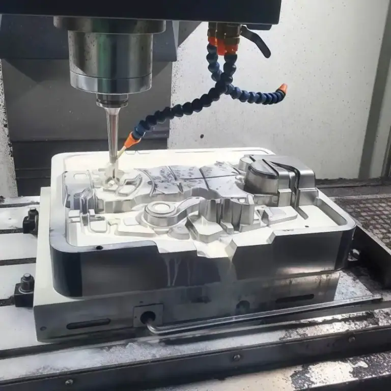
Milling: Uses rotating cutting tools to carve surfaces, slots, and cavities. It’s ideal for prismatic or complex 3D shapes. For example, in my daily work, aluminum housings with ±0.01 mm tolerances are milled using 5-axis centers to achieve precise contours and smooth finishes.
Turning: Spins the workpiece while a stationary tool cuts away material, producing cylindrical or conical shapes. This method is perfect for shafts, bushings, and valve bodies, where concentricity is critical.
Drilling: Forms holes using drill bits, with diameters typically ranging from 0.5 mm to 50 mm. Deep holes often require step drilling or coolant-through tools to ensure accuracy and chip evacuation.
In modern factories, these operations often combine automatically — milling, turning, and drilling in one setup — dramatically improving efficiency and accuracy.
Common Types Of CNC Machines
CNC machines vary by the number of movement axes:
2–3 Axis Machines: These are the most common and cost-effective. Ideal for flat parts and simple cavities, they move in X, Y, and Z directions.
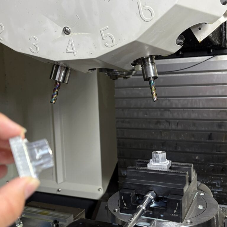
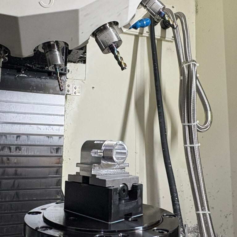
4–5 Axis Machines: Offer additional rotation and tilting movements, enabling machining of multiple faces or complex curved surfaces in one setup. For instance, aerospace components or titanium implants often require 5-axis simultaneous machining for accuracy and consistency.
Hybrid and Multi-tasking Machines: Combine milling, turning, and sometimes grinding or laser cutting in a single unit, minimizing setups and human error.
At TiRapid, we typically choose equipment based on part geometry and tolerance demands. For prototypes, 3-axis offers speed; for complex parts or production, 5-axis ensures dimensional consistency and cost savings over multiple fixtures.
What Is Designing For CNC Machining
Before production starts, design determines manufacturability. Designing for CNC Machining aims to make parts faster, easier, and more cost-effective to produce while meeting all functional and visual goals. Optimized design reduces tool paths, setups, and complexity, improving precision and delivery speed.
The Role Of Design In The Manufacturing Cycle
Design shapes every phase of the production process:
Defines Toolpaths and Complexity: Geometry, wall thickness, and tolerance affect tool choice and cycle time. Smart design can cut machining time by over 30%.
Reduces Setups and Clamping Operations: Considering accessibility and standard fixtures during design improves stability and efficiency.
Enhances Precision and Repeatability: Clear datum references and consistent alignment reduce variation. At TiRapid, standardizing reference holes lowered re-fixture errors to ±0.01 mm.
Enables Digital Manufacturing Integration: Modern CNC workflows link design, CAM, and inspection data to maintain accuracy through the entire process.
How Design Impacts Cost And Lead Time
Every dimension you draw affects production cost and timing:
Material and Geometry Drive Cutting Time: Deep pockets or thin walls increase tool wear. Reducing depth by 10% can cut cost by roughly 15%.
Tight Tolerances Increase Cost: Standard ±0.05 mm tolerances are fast; ±0.01 mm doubles the process time.
Simplified Design Accelerates Delivery: TiRapid’s DFM reviews reduced average lead times by 2 days through design adjustments like chamfers and fillets.
Standardization Saves Time: Using standard threads, hole sizes, and blanks streamlines quoting, sourcing, and manufacturing — especially for global production.
What Are The Advantages And Limitations Of Designing For CNC Machining
Designing for CNC Machining offers unmatched precision and repeatability, allowing complex geometries to be produced efficiently. However, factors like tool geometry, reach, and machine travel impose limits. Understanding these boundaries—and how to design around them—ensures high-quality, cost-effective production.
Advantages
Design is the foundation of cost, speed, and quality.
Automation and Precision: CNC systems achieve repeatability within ±0.01 mm, ideal for consistent parts such as valve housings or robotic joints.
Material Versatility: CNC machining handles metals and plastics alike by adjusting feeds and speeds.
Shorter Prototyping Cycles: Early DFM validation helps predict cutting forces and tool paths; TiRapid cut prototype lead times by 60%.
Data Integration: CAD-to-CAM workflows ensure design intent is preserved through manufacturing and inspection.
Limitations
Even advanced CNC systems face geometric constraints.
Tool Shape: Round tools can’t cut sharp internal corners; a corner radius ≥1.3× tool diameter is required.
Reach Limitation: Deep pockets beyond 3× tool diameter cause chatter, raising surface roughness from Ra0.8 to Ra3.2.
Machine Travel: Oversized parts or multi-sided features often need multiple setups, increasing error risk.
Solutions: Design Optimization Strategies
Pocket Ratio: Keep depth-to-width ≤3:1 to reduce tool deflection.
Corner Radii: Increase fillet radius (e.g., R1.5→R2.0) to extend tool life.
Thin Walls: Use ≥0.8 mm for metals, ≥1.5 mm for plastics to prevent vibration.
Hole Design: Depth ≤4× diameter; leave clearance at the bottom of blind holes.
Threads: Leave unthreaded sections 1.5× pitch deep.
Text: Use 20-pt sans-serif fonts with engraved, not embossed, text.
Ribs & Bosses: Thickness ≈60% of adjoining wall to prevent warping.
Chamfers & Fillets: Use global “break all edges” notes for efficiency.
Draft Angles: Add 1–2° on vertical walls to reduce cutting stress and improve finish.
How To Determine Key Machining Parameters During Design
In Designing for CNC Machining, design decisions define precision, cost, and lead time. By setting tolerances, finishes, materials, and stock sizes early, engineers ensure manufacturability and efficiency—turning design intent into reliable, high-precision, and cost-effective production.
Tolerances And GD&T Applications
Tolerances are the bridge between design and manufacturing.
Tolerance Drives Cost: Not every feature needs ±0.01 mm accuracy. TiRapid saved 25% machining time by setting ±0.02 mm on fit areas and ±0.1 mm elsewhere.
GD&T Improves Clarity: Instead of linear tolerances, GD&T defines geometric features such as parallelism, runout, and position.
Best Practices:
Use IT7–IT8 for critical fits.
Loosen to IT10–IT11 for non-critical areas.
Define general tolerance notes in the drawing to reduce miscommunication.
Proper tolerance allocation can reduce total machining cost by 10–30%.
Surface Finish And Aesthetic Requirements
Balancing function and appearance ensures better customer satisfaction.
Surface Roughness Impacts Cycle Time: Ra 0.8 µm requires fine finishing passes, while Ra 3.2 µm can be done in one cut.
Common Finishes:
Aluminum: Anodizing (Type II/III) for corrosion resistance.
Steel: QPQ or black oxide for anti-rust protection.
Plastics: Polishing or bead-blasting for appearance.
Design Tip: Clearly separate functional and cosmetic surfaces in your CAD model to avoid unnecessary finishing.
Material Selection And Heat Treatment
Material defines machinability and tool performance.
Cutting Behavior:
Aluminum (6061, 7075): 500–800 m/min cutting speed.
Stainless steel (304, 316): slower at 150 m/min.
Titanium (Ti-6Al-4V): requires rigid tooling and coolant.
Heat Treatment:
Hardened (>45 HRC) materials need coated carbide tools.
Stress-relieve annealed parts before final machining.
Choosing the right material and treatment can extend tool life by 2–3×.
Why Standard Stock Sizes Reduce Costs
Selecting standard stock sizes is one of the simplest cost-saving methods.
Less Machining = Less Time: A 25 mm billet vs. 30 mm saves 20% cutting time for a 20 mm-thick part.
Readily Available: Common sizes like 100 × 100 × 20 mm aluminum plates are widely stocked.
Shorter Lead Times: Avoiding custom blanks can cut procurement from 7 days to 1–2 days.
TiRapid achieved 30% faster delivery and higher material efficiency by standardizing stock dimensions.
How To Design For Different Machining Processes
In Designing for CNC Machining, each process—milling, turning, and drilling—requires unique design considerations. Smart designs minimize tool stress, reduce vibration, and simplify setups, improving accuracy and surface finish. Below are key design insights from TiRapid’s real-world manufacturing experience.
Milling Design Tips
Milling is versatile but sensitive to tool rigidity and geometry.
Control Depth-to-Width Ratio: Keep cavity depth within 4× the tool diameter. TiRapid improved surface quality by 30% on 7075 aluminum by limiting the ratio to 2.5×D.
Tool Diameter: Shorter tools offer better stiffness. Design features around standard diameters (Ø6, Ø8, Ø10 mm) to avoid costly custom cutters.
Corner Radius Optimization: Use an inner corner radius ≥⅓ of cavity depth (e.g., R4 for 12 mm depth). Larger radii reduce tool stress and chatter marks.
Turning Design Tips
Turning excels at producing round parts but requires attention to stability.
Slenderness Ratio: Keep part length-to-diameter ratio ≤8:1. For long shafts, TiRapid uses steady rests or dual centers for support.
Symmetry Matters: Symmetrical geometry ensures balanced cutting forces and prevents eccentricity.
Vibration Control: For hard materials (e.g., SUS420, HRC50), use lower spindle speeds and proper coolant.
Design Note: Add “Center Support Required” to drawings for better process planning.
Drilling Design Tips
Drilling is fundamental but often overlooked.
Depth-to-Diameter Ratio: Keep hole depth ≤10× diameter. For deeper holes, drill from both sides or use step drilling. TiRapid achieves ±0.02 mm accuracy using 5×D drills with chip evacuation cycles.
Perpendicularity: Drill entry surfaces must be flat and perpendicular to avoid wandering. Add a small spotface on angled surfaces.
Avoid Half-Holes: Half-holes damage tools and leave burrs. If unavoidable, consider milling or EDM instead.
How To Design Undercuts And Complex Features
In Designing for CNC Machining, undercuts and internal geometries pose major challenges. These hidden areas are hard to reach with standard tools and can raise costs or cause errors. Smart design balances function with tool accessibility. This section shows how to simplify or split parts to save time and cost.
Undercut Dimensions, Tooling, and Accessibility
Undercuts are classic “hidden geometries.” If not designed properly, they can make a part unmachinable.
Size Guidelines:
Keep undercut depth ≤70% of tool neck length and width ≤1.5× tool diameter. At TiRapid, adjusting a valve housing’s undercut depth from 8 mm to 5.5 mm allowed machining with a standard ball end mill—saving 25% of production time.
Tooling and Paths:
Use T-slot or ball-end mills for undercuts. In tight spaces, choose long-neck cutters or 5-axis setups. Always provide at least 1.5× tool diameter clearance for safe tool exit.
Accessibility Check:
Simulate tool paths in CAD/CAM software. TiRapid engineers use Fusion 360’s Tool Accessibility Map to identify blind zones before programming, preventing costly rework.
Cost-Effective Alternatives
Complex geometries don’t always require expensive 5-axis machining. Design optimization can often achieve the same result more efficiently.
Re-Design the Structure:
If an undercut serves only as a locking or assembly feature, replace it with chamfer-fit or threaded designs. For example, TiRapid re-engineered an aluminum housing using a 45° slide-in fit, switching from 5-axis to 3-axis machining and cutting part cost by 40%.
Split Machining & Assembly:
Divide the part into multiple sections for easier access, then rejoin with screws or welding. This “modular” approach is popular in aerospace and automation.
Pros: Lower equipment cost and easier maintenance.
Tip: Add dowel holes for accurate alignment during assembly.
Hybrid Manufacturing:
For extremely complex internal cavities, combine 3D printing for shape validation with CNC finishing on functional surfaces. This hybrid approach balances design freedom and precision—ideal for moldmaking and medical devices.
How To Plan Part Orientation And Fixturing
In Designing for CNC Machining, part orientation and fixturing strongly influence accuracy, efficiency, and cost. Good design anticipates how parts are clamped and accessed. Clear datums and fewer setups enhance repeatability, shorten cycle time, and ensure consistent machining quality.
Datum System And Fixture Positioning
Defining datums aligns design intent with machining reality. Poorly chosen datums lead to frequent repositioning and alignment errors.
Establish a Clear Datum System
Choose a functional or assembly surface as your primary datum. For instance, TiRapid machines robotic joint housings using the mounting surface as the main datum and two locating holes as secondary datums, achieving <0.02 mm assembly deviation.
3-Point Location Principle
Apply the “3-2-1” rule—three points for a plane, two for direction, one for rotation. This provides stability and keeps re-clamping error under ±0.01 mm.
Fixture Design and Selection
For production runs, use pneumatic or vacuum fixtures to speed up part changes. For prototypes, standard vises or soft jaws work well. TiRapid’s DFM reports often highlight “Fixture Interference Areas” to prevent clashes between design features and clamping zones.
Reducing Setups And Tool Changes
Every setup or tool change introduces potential error and adds time. Smart orientation and process sequencing can eliminate inefficiency.
Minimize Setups
Design so that most features (70%+) can be machined in one setup. Group critical holes and surfaces in a single coordinate system to reduce reorientation. TiRapid once reduced an aluminum base from 3 setups to 1, cutting lead time by 2 days.
Optimize Tool Change Strategy
Group features requiring the same cutter size or depth. In 5-axis machining, TiRapid uses Ø8 mm for roughing, then Ø4 mm and Ø2 mm for finishing—saving 15% cycle time and improving tool life.
Choose Efficient Machining Orientation
Whenever possible, orient parts so the primary surface faces upward for better chip evacuation and less tool deflection. For angled features, tilt the part to allow normal cutting paths, improving surface finish and consistency.
How To Prepare CNC Machining Drawings and Files
In Designing for CNC Machining, drawings and 3D files connect design and manufacturing. Clear, standardized documents help machinists understand intent immediately, minimizing rework and improving precision. This section outlines key drawing details and file formats for fast, accurate quoting.
What To Include In Your Drawings
A well-prepared technical drawing ensures that every machined part meets its design intent.
GD&T (Geometric Dimensioning and Tolerancing)
Use geometric tolerances like position, perpendicularity, and concentricity to express functional requirements. TiRapid engineers verify all GD&T symbols before machining to ensure they match our equipment capability.
Dimensional Tolerances:
Follow common standards such as ISO 2768-mK or ASME Y14.5. Typical guidelines:
General machining: ±0.1 mm
Precision fits: ±0.02 mm
Hole tolerances: H7 or H8
Applying these standards helps balance cost and accuracy.
Surface Finish & Treatment:
Always specify Ra values and finishing types, e.g.:
Ra 3.2 μm for general machining
Ra 0.8 μm for polishing
Type II black anodizing or QPQ black oxide for protection
TiRapid automatically assigns tooling and process parameters according to surface requirements.
Recommended File Formats And Upload Tips
Choosing the right format accelerates quoting and prevents translation errors.
3D Model Formats
STEP (.stp/.step) — universal, preferred for CNC
IGES (.igs) — for complex surfaces
STL (.stl) — for 3D printing, not ideal for CNC quoting
Parasolid (.x_t) — ideal for SolidWorks/NX users
2D Drawing Formats
PDF — for notes, tolerances, surface finish
DWG/DXF — for laser cutting or wire EDM
Pre-upload Checklist
Consistent units (mm or inch)
Remove unused bodies or hidden sketches
One part per file
Verify alignment between drawing and 3D model
Include surface finish and treatment notes
Following these file standards ensures that your CNC machining project moves from design to production seamlessly and accurately.
How To Ensure Machining Quality And Precision
In Designing for CNC Machining, quality assurance goes beyond final inspection—it spans from design to delivery. Each step, from tool choice to surface verification, impacts accuracy and consistency. This section shows how to ensure CNC parts meet functional and visual standards.
Measurement Methods And Tools
Precision machining depends on reliable inspection methods tailored to tolerance requirements and part geometry.
Contact Measurement (CMM)
Coordinate Measuring Machines (CMMs) provide micron-level precision:
Accuracy up to ±2 µm
Ideal for complex geometries and freeform surfaces
Automated 3D comparison reports for faster validation
Non-Contact Optical Measurement
Optical and laser scanning capture millions of surface points in seconds:
Accuracy around ±10 µm
Ideal for aesthetic or flexible components
Quickly generates a 3D cloud map for dimensional verification
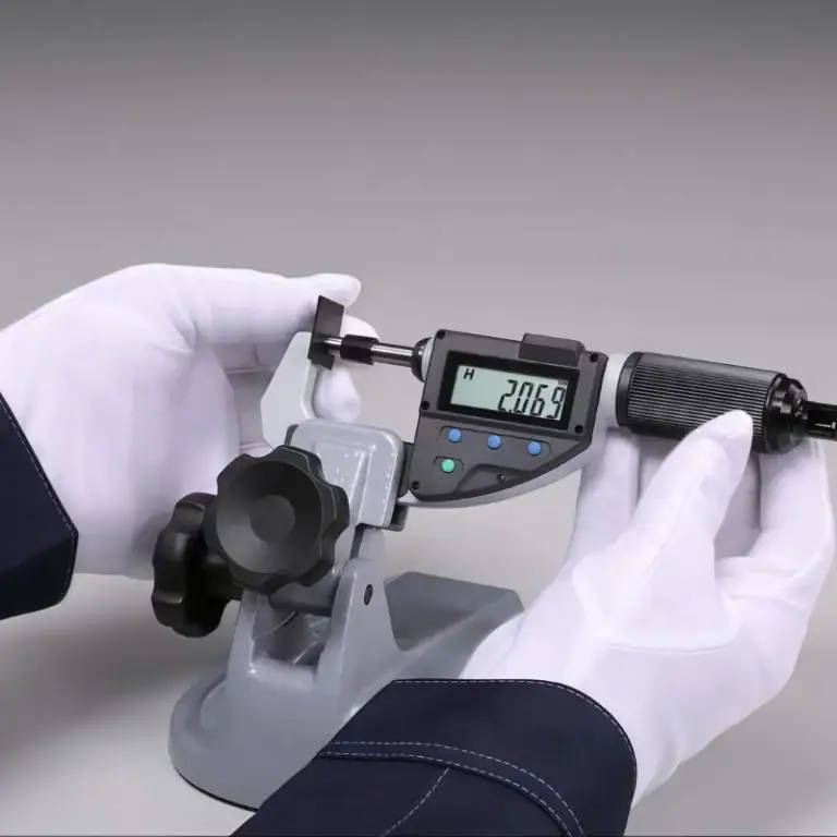
Manual Measurement
For less demanding tolerances (>0.05 mm), calipers and micrometers provide sufficient accuracy.
Example: Measuring a 6061 aluminum housing with ±0.05 mm fit tolerance using a Mitutoyo digital micrometer.
Finished Part Quality And Appearance Expectations
High-quality CNC parts combine dimensional precision with surface perfection.
Surface Roughness Standards
Ra 3.2 μm: Standard milled finish
Ra 1.6 μm: Fine machining
Ra 0.8 μm: Polished or mirror finish
Visual and Cosmetic Inspection
Checks include scratches, dents, burrs, and discoloration.
Minor color variations (ΔE < 2.0) in anodized finishes are acceptable within ISO standards.
Dimensional and Form Accuracy
Using SPC (Statistical Process Control), TiRapid monitors tool wear and adjusts offsets in real time, keeping deviations within ±0.005 mm during mass production.
By combining CMM inspection, SPC analysis, and cosmetic evaluation, manufacturers achieve consistent, high-quality CNC parts with minimized rework and improved customer satisfaction.
FAQs
What Software Is Used To Design CNC Parts?
I mainly use CAD software like SolidWorks, Fusion 360, or AutoCAD for 3D modeling and CAM tools like Mastercam or NX CAM for toolpath generation. These platforms integrate design and manufacturing, improving precision by up to 30% and reducing programming time by 40% through automated G-code generation.
What Are The Criteria For Designing CNC Machine Tools?
When designing CNC machine tools, I prioritize rigidity, spindle speed, and thermal stability. A rigid structure ensures vibration control within ±2 µm, while balanced speed-torque ratio enhances machining efficiency by 25%. I also consider load capacity, tool change time, and maintenance accessibility for production stability.
How Can I Optimize My Design For CNC Machining?
I optimize my design by aligning geometry with standard tool sizes and machinable radii. Avoiding deep cavities and minimizing setups reduces cycle time by up to 35%. Using Design for Manufacturability (DFM) principles early in CAD ensures smoother tool paths, better surface finishes, and fewer tool changes.
How Can I Enhance The Cost-Efficiency Of My CNC Machining Design Project?
To boost cost-efficiency, I simplify part geometry, standardize hole sizes, and design for single-setup machining. Material utilization and tool life monitoring can save 15–25% in production costs. I also group similar operations and use multi-axis setups to cut labor and fixture expenses significantly.
How Can I Ensure Tight Tolerances In My CNC-Machined Parts?
Ensuring tight tolerances (as close as ±0.005 mm) by controlling cutting temperature, using CMM inspection, and programming tool wear compensation. Precision fixturing, stable materials like 6061-T6 aluminum, and post-process verification help maintain dimensional consistency across multiple production runs.
Conclusion
Designing for CNC Machining is not just about drawings and dimensions—it’s about balancing precision, efficiency, and cost. By considering tool accessibility, tolerances, materials, and fixturing early, engineers can minimize risks, improve consistency, and achieve high-precision parts more economically.Do you have any ideas or needs regarding CNC machining design? Your contact will become our valuable experience!