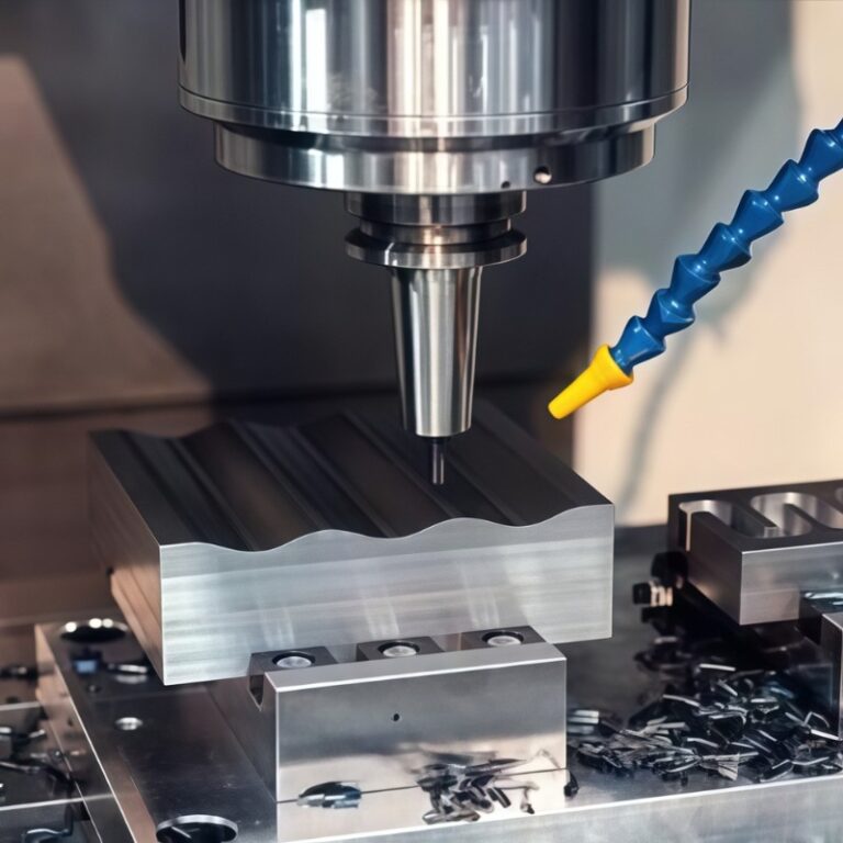
Contour milling has become one of the core technologies for achieving complex shapes and high-precision curved structures. Whether it is the 3D curved surface of aerospace structural parts, the cavity envelope of the mold edge, or the smooth outer contour of medical implants, the processing process is almost inseparable from the support of contour milling. Compared with traditional face milling or slot milling, contour milling emphasizes precise cutting along the part shape path, and is more suitable for parts with complex geometries or high-quality surface requirements. I will focus on the definition, process flow, common tools and typical application industries of contour milling to help you fully understand its technical advantages and practical application value.
What Is Contour Milling
Contour milling is a CNC milling method that uses the part’s outer contour or spatial surface as the target path for processing. It is often used to manufacture precision parts with complex two-dimensional or three-dimensional geometric features. Unlike traditional milling, which focuses on plane or inner cavity cutting, contour milling focuses more on orderly and continuous cutting along the characteristic paths such as part outer curves, bevels, inclined walls, and fillets to achieve precise structures and clear edges.
In my processing practice, contour milling is widely used in mold manufacturing, medical equipment, aviation structural parts and mechanical housings, especially in controlling geometric accuracy (usually required to be within ±0.01 mm) and surface roughness (such as Ra 0.4 μm or less). Its core advantages are strong path controllability, diverse cutting surfaces, and both processing efficiency and quality.
In addition, contour milling is often used in conjunction with multi-axis linkage CNC machine tools (such as 3-axis, 4-axis or 5-axis), and through tools such as ball-end milling cutters and round nose cutters, high-degree-of-freedom tool movement can be achieved on inclined surfaces, curved surfaces and non-planar contours. Compared with traditional end milling, which is only applicable to rectangular boundary cutting, contour milling can handle almost all structural processing of non-straight boundary.
It is worth noting that it is also significantly different from cavity milling: cavity milling focuses on “internal material removal” and is mainly used to make holes and grooves, while contour milling emphasizes “shape retention” and pursues smooth boundaries and clear contours. When the product needs to ensure the integrity of the appearance, assembly accuracy or surface continuity, I usually give priority to contour milling.
In general, contour milling is not only the core means of processing highly complex products, but also a key process to improve the surface quality, geometric consistency and assembly interchangeability of parts. Understanding its essential characteristics, equipment requirements and typical applications is the only way to move towards high-end CNC machining.
Contour Milling Process
Contour milling is not a simple “walking along the edge”, but a complete CNC machining process. From the tool path setting of the CNC program, to the selection of tools and cutting parameters, to workpiece clamping, cooling and lubrication, layered processing, finishing, and final dimensional inspection, each step plays a decisive role in the quality and efficiency of the finished product. In my experience, a stable contour milling process can control the accuracy within ±0.01 mm, the surface roughness reaches Ra 0.4 μm, and the scrap rate is less than 1% .
The whole process usually starts with contour extraction of the CAD model and path planning in CAM software, and efficient tool paths are developed in conjunction with tool diameter, tool direction (Climb or Conventional) and feed rate. The next step is tool selection and parameter setting. I usually choose a ball-end mill or a round nose cutter according to the material type and surface requirements, and set a reasonable spindle speed (such as 6000-12000 RPM) and feed rate (such as 800-1500 mm/min).
Next is workpiece clamping and error control. Especially for long strips or thin-walled structures, I will use a 3-point positioning + soft pad clamping strategy to prevent vibration and deformation. During processing, I usually use a layered cutting method with a depth of cut of 0.3-0.8 mm per layer to reduce tool load and improve contour consistency. The cooling method depends on the material and tool. For example, MQL is used in aluminum processing, and high-pressure cooling is used in titanium alloys.
Finally, by combining finishing with on-machine measurement, I monitor dimensional deviations in real time to ensure that the product meets the accuracy requirements of the drawing. The complete contour milling process not only improves part quality, but is also the key foundation for ensuring production efficiency and repeatability. Mastering this systematic approach is the core capability to move from traditional milling to high-precision machining.
Different Types Of Contour Milling Processes
Contour milling is not a single process, but a systematic process consisting of multiple machining stages. Each stage – from roughing, semi-roughing, semi-finishing to final finishing and super finishing – has different tasks, the purpose of which is to balance removal rate, machining efficiency and surface quality. In actual projects, I found that if the tool path strategy and cutting parameters of each stage can be reasonably allocated according to product requirements, the overall machining efficiency can be improved by about 30% while maintaining a dimensional accuracy of ±0.01 mm. H3 Roughing and semi-roughing
Semi-Finishing
Control margin to ensure accuracy
In semi-finishing, I usually reserve 0.3-0.5 mm of allowance. This step is the bridge between roughing and finishing, and it can effectively correct surface ripples and dimensional errors. Especially in complex surfaces or large-sized parts, reasonable allowance control can stabilize the final tolerance within ±0.02 mm and avoid the risk of subsequent cutting overload or undersize.
Choose a short blade
I prefer to use short-edged ball-end tools, such as φ6-φ10 mm ball-end end mills or milling cutters with chamfered edges. These tools are more rigid and have good vibration resistance. For different materials, I choose different tool materials and coatings, such as cemented carbide + TiAlN coating, which can extend the life of the tool by 30% when processing mold steel or titanium alloy.
Parameter adjustment for steady speed
Parameter setting needs to take into account both efficiency and stability. I usually set the cutting depth ap to 0.5–1.5 mm and the cutting width ae to 40–60% of the tool diameter. For aluminum alloys, 8000–12000 RPM and a feed of 1000–1500 mm/min can be used; for steel, the speed is controlled at 4000–6000 RPM to avoid thermal deformation.
Tool path sequence
I often use contour or Z-axis equidistant layer cutting path to avoid uneven texture caused by reverse cutting. The cutting sequence is controlled in one direction, slow in and slow out, especially in the 3D surface area, the use of continuous curve transition path can effectively improve the surface consistency.
Thermal protection knife jump
High temperature is a killer of precision. I generally use atomized cooling or MQL lubrication to reduce the deviation caused by thermal expansion of the tool. During long processing, I set stage pause points to check thermal drift and program tool compensation paths in the inner corner area to avoid residual material and surface chipping.
Finishing
Precision goals first
The core task of the finishing stage is to achieve the final size and surface quality. I usually control the tolerance within ±0.01 mm, and even ±0.005 mm for high-end parts such as aerospace connectors or medical housings. At this time, any path error, tool wear or thermal deformation must be controlled within a very small range.
Cut slowly with a knife
I prefer to use small diameter ball end mills or R-angle cutters with diameters of 1–4 mm, which are especially stable on 3D curved surfaces or structures with many chamfers. Small cutters mean lower cutting forces and less vibration, which is suitable for thin-walled and easily deformed parts. In titanium or stainless steel parts, slow cutting with a small knife is my key strategy to ensure smooth finish.
Parameters are gentle and stable
Finishing is not about material removal efficiency, but cutting stability. I usually control the cutting depth ap to 0.2-0.5 mm, and the cutting width ae to no more than 20% of the tool diameter. The spindle speed is controlled at 6000-12000 RPM, and the feed rate is 500-1000 mm/min to ensure that each pass is repeatable and predictable.
Avoid impact when cutting
I tend to use the same downward cutting and smooth transition path to avoid sudden stops or reverse cutting. The commonly used tool path type is “contour line + projection refinement”, especially on free-form surfaces with continuously changing curvature, which can avoid grain breaks or mutations and improve overall consistency and appearance quality.
Smoothness depends on lubrication
Lubrication is the key to improving surface quality. When processing aluminum alloys, I use oil mist lubrication + strong air blowing to obtain a surface roughness of Ra0.4-0.6μm; while for stainless steel and engineering plastics, I choose micro-lubrication combined with intermittent chip cleaning to prevent chip accumulation and secondary scratches on the blade.
Error detection
Finally, I will use a three-dimensional or contact gauge to recheck the key dimensions. For high-demand parts, automatic tool compensation + real-time coordinate correction will be added to the program to ensure that the machining error is controlled within the set tolerance. Regularly checking the tool wear status is also an important guarantee for the stability of finishing.
Super Finishing
Just for the ultimate surface
When customers require a surface roughness lower than Ra0.2μm, or an optical-grade surface with no visible knife marks, I will adopt a super-finishing strategy. This is very common on parts such as mold cavities, aerospace surfaces, and orthopedic implants. The main purpose is to improve assembly accuracy and surface performance while reducing post-processing costs.
Very small tools, very tight paths
I usually choose a φ0.5-1.5 mm ultra-fine ball-end tool and use a step size of 0.05-0.1 mm for contour finishing. The path arrangement is mainly based on “smoothing + micro-overlapping”. The tool path is like “sweeping the surface”. Each layer is like a polishing cloth gently brushing the surface, leaving no mechanical traces.
High speed, low feed
The speed needs to reach 12000-20000 RPM, the feed is controlled at 300-600 mm/min, and the maximum cutting depth is only 0.1 mm or less. Although this parameter setting has low processing efficiency, it can minimize vibration and heat accumulation, which is the key to obtaining a mirror effect.
The most important thing is “stability”
I pay special attention to the machine tool status and environmental temperature control. The machine tool must have a thermal compensation system and a high-precision screw. The coolant must be kept at a constant temperature to avoid dimensional fluctuations caused by thermal expansion and contraction. At the same time, I will re-clamp before each super-finishing to ensure that there is no debris or floating between the part and the workbench.
Detection by optics
After processing, I usually use a white light interferometer or a three-dimensional scanning head for non-contact measurement to check the surface finish and 3D topography. For parts that require medical-grade certification, residual stress testing and cleanliness verification are also required to ensure that the product is free of residual particles and surface contamination.
2D vs. 3D Milling
2D milling: efficient solution for regular geometries
In my daily processing, 2D contour milling is mainly used to process planar geometric shapes such as outer contours, slots, shoulder structures, etc., and is particularly suitable for mechanical housings, plates and structural parts. Its path is simple, the processing speed is fast, and the tool selection range is wide, which is suitable for mass production.
I often use flat-bottom end mills or round nose cutters, with equal height or single-sided paths, combined with precision control within 0.1 mm, and can quickly meet the standards for materials such as carbon steel, aluminum alloy, and ABS.
3D milling: the home of complex surfaces and free curves
3D contour milling is an indispensable method for solving complex spatial structures (such as mold cavities, blades, and shell streamline structures). The tool path not only moves in the XY direction, but also combines the Z-axis variable depth tool path to construct a free-form surface.
In 3D processing, I prefer to use a ball-end end mill and a five-axis linkage path, with a layer step of 0.01mm, to perform continuous envelope milling on the surface. Especially when processing aviation titanium alloys and orthopedic implants, 3D contour milling must be used to achieve precise fitting.
The parameters are significantly different from the machine tool requirements
| Comparison Items | 2D Contour Milling | 3D Contour Milling |
| Processing object | Regular plane contours, slots | Curved surface, inclined surface, free form |
| Tool Type | Flat knife, round nose knife | Ball end cutters, taper cutters, compound angle cutters |
| Accuracy range | Typically ±0.05 mm | Up to ±0.01 mm, depending on the five-axis linkage capability |
| Programming Difficulty | Simple, 2.5 axis is enough | High, CAM system needs to support surface processing and interference avoidance |
| Processing efficiency | High, suitable for batch | Medium to low, suitable for high value-added customized parts |
| Common Applications | Shell frame, bracket plate, slotted parts | Complex parts such as molds, medical implants, aerodynamic components, etc. |
How do I choose 2D or 3D
When the customer only provides a basic structural drawing and the tolerance requirement is within ±0.05 mm, I will give priority to 2D milling to reduce costs; but once it involves free-form surfaces or the need to control assembly transitions, I will choose 3D without hesitation, and use 3D scanning and proofreading during processing to ensure accurate matching of the morphology.
Common Tool Types
In my many years of experience in contour milling, the choice of tool not only affects the processing accuracy and efficiency, but also directly determines the surface quality and tool life of the product. Different processing stages (roughing, semi-finishing, finishing) require tools with different structures and materials. Especially in complex contours or high-hardness materials, the tool shape, coating and structure determine the success or failure of the project.
Interchangeable Ball Head Tool
This tool structure consists of a tool holder and a replaceable tool head, which is suitable for high-precision three-dimensional contour processing. I usually use it in five-axis CNC machining to process mold surfaces or titanium alloy frame structures.
Advantages :
Reduce overall tool costs: only replace worn tool heads
High rigidity connection, suitable for high load scene
applications : mold cavity, complex aviation structure parts
Precision performance : surface roughness can reach Ra0.4μm or less
Solid Ball End Mills
Suitable for high dynamic contour processing, I prefer to use it with a high speed spindle (>15,000 rpm), especially suitable for cutting soft metals such as aluminum and copper.
Advantages :
High concentricity, suitable for micro feature processing
No tool head interface to avoid clamping errors
Applications : Medical implants, delicate parts of electronic parts
Typical size : Tool diameters range from Ø0.5mm–Ø12mm
Circular Blade Knives
This type of tool uses an indexable round insert and is suitable for roughing and medium-precision contour milling. I use it more frequently when processing stainless steel or high-hardness steel.
Advantages :
Smooth cutting and little vibration
The blade angle is flexible and adjustable to adapt to different cutting depths .
Disadvantages : Not suitable for very small R angles or detailed features
Indexable Ball End Tool
Combining ball head geometry with indexable insert structure, it takes into account both 3D topography processing and insert economy. I recommend it for high-volume contour projects that are sensitive to tool usage costs.
Advantages :
Easy to replace, no need to replace the whole
Suitable for machining steel parts and high temperature alloys .
Limitation : High tool clamping accuracy is required.
The Difference Between Roughing Tools And Finishing Tools
When setting up the tool library, I will strictly distinguish between tools used for rough machining and finishing to avoid accumulation of machining marks or errors.
Rough machining tools : Most of them adopt large helix angle, strong chip removal design, large tool diameter, and machining allowance is usually 0.5-1.5mm
Finishing tool : small tip radius, tool coating adapted to high surface requirements, suitable for light cutting, accuracy up to ±0.01mm
Key Factors Affecting Contour Milling
In contour milling projects, I always optimize material properties, machine tool performance, tool status, cutting parameters and cooling control as key variables. These factors directly determine surface quality, machining efficiency, dimensional stability and tool life. Especially in multi-axis machining and complex curve conditions, any inconsistency may lead to error accumulation, workpiece scrapping or machining interruption.
Material Type And Machinability
Different materials exhibit completely different machining characteristics for contour milling. For example:
Aluminum alloy : high thermal conductivity, suitable for high-speed milling, recommended cutting speed > 400 m/min.
Titanium alloy : prone to built-up edge and thermal deformation, it is recommended to use a small cutting depth and multiple light cutting methods.
Stainless steel : Severe work hardening requires the use of wear-resistant tools and appropriate lubrication.
I usually set the tool path strategy and cooling method based on the material’s HB hardness, thermal conductivity and chip breaking properties.
Machine Tool Rigidity And Control System
Machine tool rigidity is one of the core factors affecting machining accuracy and stability. When using a vertical three-axis or five-axis machining center, I pay special attention to the following parameters:
Spindle power and torque
Is the guide rail structure a linear rail or a hard rail?
Whether the CNC system has real-time compensation (such as Siemens 840D or FANUC 31i)
is insufficiently rigid, it will cause chatter, contour deformation and even tool breakage, especially when the workpiece is large or clamped with long overhangs.
Tool Life And Coating Technology
When I evaluate tool life, I focus on wear uniformity, coating peeling and thermal cracking. Current mainstream coatings include:
TiAlN : High temperature resistant, suitable for dry cutting
AlCrN : Suitable for stainless steel and hard materials
DLC coating : Low friction, suitable for aluminum.
During the processing, if the edge wear exceeds 0.1 mm, I will replace the tool immediately to avoid dimensional drift and surface burns.
The influence Of Cooling Strategy On Processing
Coolant not only reduces temperature, but also affects lubrication and chip removal. In contour processing, I often use the following three methods:
High-pressure internal coolant (70–120 bar): for deep cavities and complex grooves
Mist cooling : used for finishing, surface roughness < Ra0.8μm
MQL (Minimum Quantity Lubrication) : Excellent in environmentally demanding or aluminum alloy applications.
Incorrect cooling can cause tool burnout, burr accumulation and contour discontinuities.
Match Feed Rate To Cutting Depth
When setting feed rate and cutting depth, I insist on following the principle of “matching material-tool-equipment”. For example:
Aluminum alloy: cutting depth 1.0–2.5 mm, feed 800–1500 mm/min
Titanium alloy: cutting depth 0.2-0.5 mm, feed 200-400 mm/min
If the feed is too fast and the cutting depth is insufficient, the processing efficiency will be reduced; otherwise, it is easy to damage the tool or burn the surface. After optimizing the matching, I have shortened the cycle time by more than 15%.
Application Scenarios Of Contour Milling
Contour milling is not only a way to process complex curves and boundaries in manufacturing, but also a key process for achieving high-quality parts in the precision industry. Whether it is lightweight processing of aviation structural parts or the pursuit of complex cavities in the mold industry, I find that contour milling is almost irreplaceable. Especially in scenarios with ±0.01 mm accuracy requirements, natural transition of three-dimensional surfaces, and surface roughness < Ra0.8 μm, it plays a decisive role.
Here are some typical industry applications I have summarized:
| Application Industry | Part Type | Key Requirements | Advantages of contour milling |
| Aerospace | Reinforced rib structures, frames, and skin parts | Lightweight, high strength, surface integrity | Suitable for 3D curved surfaces, large thickness changes, and requires five-axis linkage |
| Mold manufacturing | Injection mold cavity, stamping mold, electrode structure | Complex cavity, high precision, clear corners | Able to achieve high-precision forming of free-form surface contours |
| Medical Devices | Orthopedic implants, surgical instrument structures | High cleanliness, biocompatibility, dimensional consistency | Suitable for titanium alloy, high surface requirements, flexible batch |
| Automobile and Electronics | Shell, decorative parts, connecting brackets | Appearance quality, assembly dimensions, curve transition | Smooth surface, clear edges, finishing before polishing |
Advantages And Limitations
Contour milling demonstrates great flexibility and precision in actual machining. I would almost always choose this process for parts with complex shapes, accuracy requirements within ±0.01 mm, and surface roughness below Ra 0.4 μm. But I also know that it is not suitable for all scenarios. Contour milling still has challenges in programming difficulty, equipment requirements, and cost control. Therefore, fully weighing its advantages and limitations is the key to improving overall production efficiency and reducing risks.
Advantages
High profile consistency
With the help of multi-axis linkage machine tools and high-precision tool path control, profile milling can achieve continuous processing of complex 3D profiles and avoid accuracy deviations caused by process switching. In actual cases, we have achieved a stable repeatability of ±0.005 mm for large aluminum shell profiles.
Excellent surface quality
In the finishing and super finishing stages, with optimized cutting parameters and lubrication methods, surface qualities of Ra 0.2–0.4 μm are the norm, which is particularly suitable for medical and automotive parts with strict requirements on vision and fit.
Capable of processing complex structures,
whether it is a free-form surface, a sharp-angled inner cavity, or a narrow area, contour milling can be handled by optimizing the tool path and using a small-diameter ball-end tool to achieve structural design that is difficult to accomplish with traditional processing.
Limitation
High programming complexity
, especially in 3D contour and multi-faceted conversion processing, the tool path needs to accurately fit the model boundary, which usually requires advanced CAD/CAM software support and a long program debugging time.
High requirements for machine tool performance In order
to maintain a stable path of the tool in the curve, a high-rigidity, high-speed, low-vibration machining center and a CNC platform with a good servo control system are required.
The high processing cost
is not only reflected in tool consumption, programming hours and equipment investment, but also includes hidden costs such as process optimization, trial cutting and machine adjustment, which is especially obvious in small-batch trial production.
FAQs
What Is Profiling In Milling?
Profiling In Milling Refers To The Process Of Machining The Outer Contour Or Complex Curved Surface Of A Workpiece. I typically Use It For 2D Or 3D Features On Aerospace, Mold, Or Automotive Parts. With Tolerances As Tight As ±0.01 mm And Surface Roughness Below Ra 0.4 μm, Profiling Ensures High Precision And Excellent Finish In Critical Applications.
What Are The Three Types Of Milling?
The Three Main Types Of Milling I Apply In CNC Machining Are Face Milling, Slot Milling, And Profile Milling. Face Milling Targets Flat Surfaces, Slot Milling Cuts Grooves, While Profile Milling Shapes The Outer Contours. Each Method Has Unique Toolpaths And Feed Strategies, Chosen Based On Geometry, Tolerance, And Material Properties Of The Part.
What Is A Mill Profile?
A Mill Profile Describes The Shape Or Geometry Machined Along The Edge Or Contour Of A Workpiece. In My Work, It Usually Refers To Toolpaths Generated To Follow A 2D Or 3D Outline Precisely. These Profiles Are Programmed In CAM Software And Executed With Ball-Nose Or Corner-Radius End Mills For Consistent Dimensional Accuracy And Smooth Transitions.
What Is The Difference Between Profiling And Milling?
Milling Is The Broad Machining Process Using Rotary Tools To Remove Material, While Profiling Is A Subset Focused On Contour Machining. I Use General Milling For Surfaces And Slots, But Profiling Specifically Targets Edge Paths Or Freeform Curves. Profiling Requires More Toolpath precision And Is Common In Parts With ±0.01 mm Tolerance Requirements.
Is Profile Milling A Common Milling Operation?
Yes, Profile Milling Is One Of The Most Common CNC Milling Operations I Perform, Especially In Aerospace, Mold, And Medical Industries. Its Ability To Create Complex Contours, Chamfers, And 3D Features Makes It Ideal For High-Precision Applications. I Often Use It With 5-Axis Machines And Ball Nose Tools For Superior Accuracy And Efficiency.
What Is The Difference Between Profiler And Sampler?
A Profiler Is A CNC Toolpath That Follows The Contour Of A Workpiece, While A Sampler Refers To A Device Or Method For Extracting Representative Data. In Manufacturing, Profilers Create Geometries, Whereas Samplers Evaluate Quality Or Properties. I Use Profilers For Precision Cuts, But Samplers Are Typically Found In Quality Control Or Testing Labs.
Conclusion
Profile Milling is an indispensable technology for high-complexity contour processing. By rationally selecting cutting tools, optimizing cutting parameters, and combining advanced CAM programming with high-rigidity equipment support, I can achieve ±0.01 mm accuracy and high-quality surface finish (up to Ra 0.4 μm) on a variety of materials such as aluminum alloy, stainless steel, and titanium alloy. Whether it is aerospace structural parts, medical parts, or electronic precision housings, profile milling shows excellent adaptability and efficiency. However, it places higher demands on machine tool performance, programming capabilities, and process control.
Correctly understanding the principles, classifications and application scenarios of contour milling is the key to improving the overall processing level. Only after fully considering materials, equipment, design requirements and cost-effectiveness can its value be maximized and a truly efficient and high-quality CNC processing process be created.