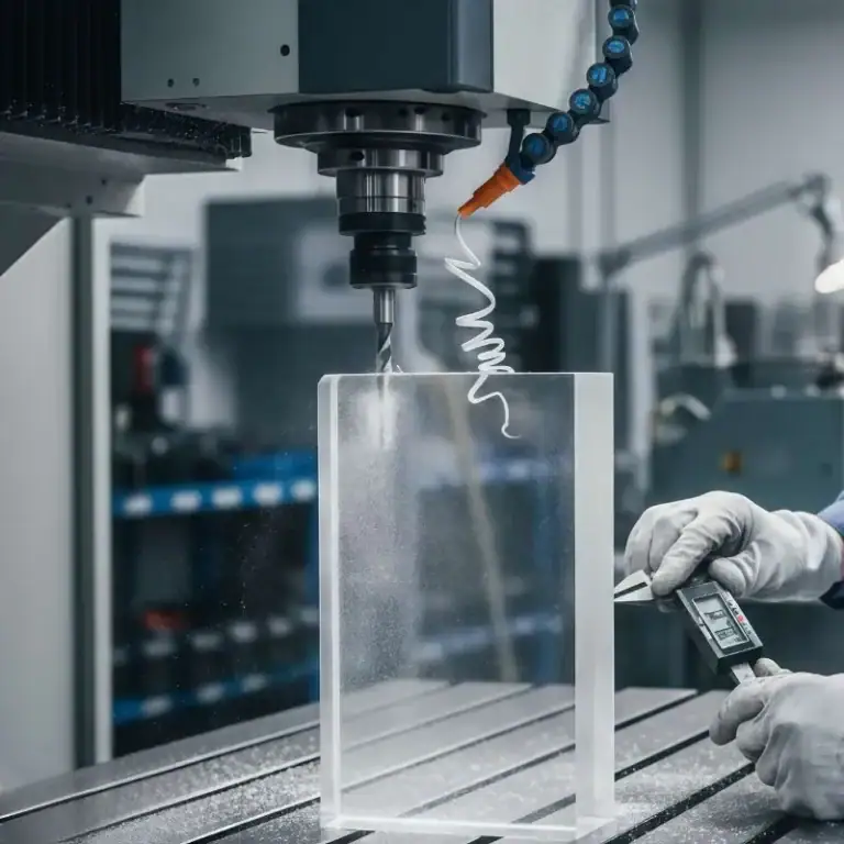
Have you ever marveled at the delicate structure of metal parts, the complex design of aerospace components, or the fine structure of medical devices? Behind these amazing precision manufacturing, CNC machining machines are largely responsible. And CNC programming is the “information link” between humans and processing machines, through which digital designs are transformed into physical products.
Essentially, CNC programming is to create a set of instructions that tell machine tools exactly what to do – how to move, at what speed, when to turn on coolant, etc. These instructions enable machine tools to process raw materials into finished products with amazing speed, accuracy and consistency.
The Language of CNC: G-Codes and M-Codes
Okay, let’s talk about the core “language” – the codes! In CNC programming, your main concern is that instructions are made up of different types of codes, each with a specific function.
G-codes (Geometry Codes)
These are all about geometry and movement. They tell the tool how to move (like in a straight line or a circle) and where to go. They control things like positioning, coordinate systems, and selecting the working plane. Think of them showing “How the tool moves in relation to the workpiece”. Examples include G00 for rapid movement, G01 for linear movement, G02/G03 for circular movement, and G90 for absolute positioning.
M-codes (Miscellaneous Codes)
These handle the machine’s actions – the stuff that isn’t directly about tool movement. They control what the machine does. This includes turning the spindle on (M03/M04) or off (M05), turning the coolant on (M08) or off (M09), and automatic tool changes (M06). M-codes show “What the machine does in the machining process”.
Auxiliary Functions
Just as important are other codes that specify details:
- F (Feed Rate): How fast the tool moves along its path while cutting.
- S (Spindle Speed): How fast the cutting tool rotates.
- T (Tool Number): Which tool to use.
- H (Tool Height Offset Number): Used with G43 for tool length compensation.
- D (Tool Radius Offset Number): Used with G41/G42 for tool radius compensation.
- N (Block or Line Identifier): Used in manually written programs to number the blocks (lines) of code. While not always strictly necessary, they help organise things.
You can see these codes in action in the examples provided in the source material, showing how they combine to make the machine perform specific operations like contour milling, face milling, roughing, and drilling.
Methods for Generating CNC Programming Language
There are a few ways to generate the G-code and M-code instructions for a CNC machine. Each has its own place depending on the complexity of the job and your skill level.
Manual Programming
This is the oldest method. It involves a programmer writing out the G-code and M-code line by line based on the part drawing and their knowledge. It requires a deep understanding of how the machine will react and visualising the outcome. It’s best for very simple tasks or highly specific, perhaps manual, designs. The big downside? It’s the most challenging, time-consuming, and has a higher chance of errors because it doesn’t automatically check for mistakes.
Computer-Aided Manufacturing (CAM) Programming
This is the most common modern method, especially for anything complex. You use specialised software that takes a 3D CAD (Computer-Aided Design) model of the part and helps you define machining strategies and calculate the necessary tool paths. The CAM software then generates the G-code automatically. It’s much faster, simpler, and more accurate than manual programming.
CAM software often lets you visualise the tool paths and even simulate the machining process to catch errors before they happen. It’s ideal for complex geometries and multi-axis machining. While the software can be pricey, it saves a lot of time and energy in the long run.
The Modern CNC Programming Workflow
Using CAM software is the standard for most industrial applications today. Here’s a typical flow:
- CAD Modelling: You start with a digital design of the part, usually created in CAD software.
- CAM Planning & Tool Paths: Load the CAD model into CAM software. Here, you define machining strategies and let the software calculate the tool paths – the exact movements the tool will make to cut the part. This is where you might select tools, define cutting speeds (S) and feed rates (F), and consider parameters for specific operations like roughing (G71) or drilling (G81).
- Verification and Simulation: This is a crucial step! You simulate the calculated tool paths within the CAM software. Modern CAM systems often use digital twins – virtual models of your specific machine, tools, and clamps – for highly reliable collision checking. Simulating material removal helps visualise the final part and ensures there are no crashes.
- Post-processing: The CAM software generates a standard output (often a CL file). A post-processor specific to your CNC machine’s control converts this into the exact G-code and M-code format your machine understands. This step requires precise configuration.
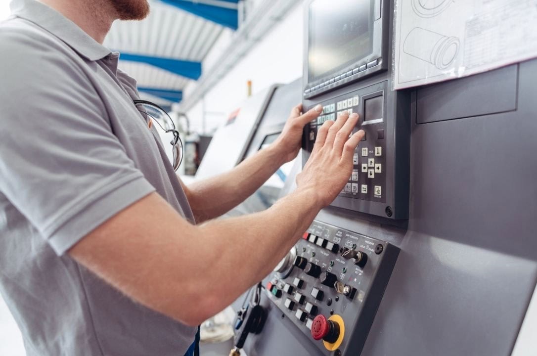
- Transfer: The finished G-code program is sent to the CNC machine’s control unit.
- Setup: The machine operator prepares the machine by installing the correct tools (T codes), setting up the workpiece, and defining the work offset (like G54) which tells the machine where the part is located in its working area.
- Check Conditions: The operator verifies things like processing conditions, modes, speeds, and accelerations.
- Machining: The machine executes the program, bringing the design to life.
how to learn cnc programing?how about dive In CNC Programming?
Jump on board new CNC machining opportunities! Beginning your study of G-code and M-code alongside CAD/CAM software instruction provides a strong basis. G-code and M-code serve to control CNC devices in workshops; mastery requires familiarizing oneself with problem solving techniques through guided practice sessions.
Learn even more by expanding your knowledge in CNC programming to cover every facet of process flow management – this begins from part design assessments for manufacturability to tool path programming, machine programming simulation and debugging, production optimization as well as multi-axis operations programming with cycle time improvements as well as solving difficult spatial configurations.
Your ideal place for realizing ideas lies with us; whether starting with prototyping or already looking for manufacturing partners, our team stands ready with precision machinery to assist regardless of project scope. Our holistic approach includes everything from consultancy and custom programming through fine machining and production-grade components – so don’t hesitate to come see us and bring all your project plans.