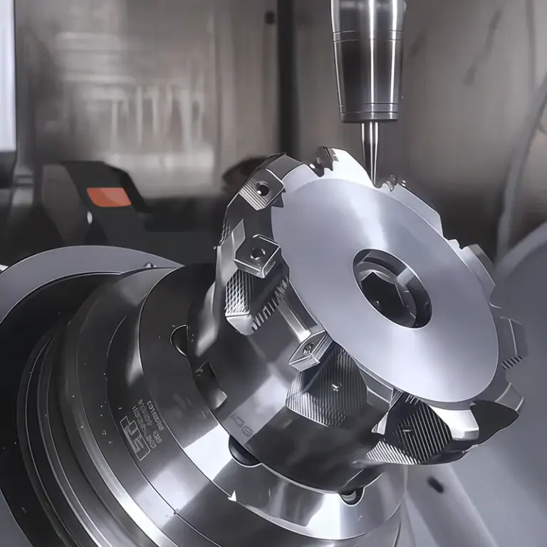
CNC turning is widely used to manufacture precision shafts, connectors, metal sleeves, threaded components, and parts for automated equipment. For buyers sourcing custom CNC turned parts, machining quality depends not only on machine accuracy but also on tool geometry, material properties, cutting parameters, workpiece clamping, and production process control. Optimizing the turning process can improve dimensional consistency, reduce burrs, chatter marks, and surface defects, while lowering tool consumption and rework costs. Developing a suitable machining strategy for each material and component design helps manufacturers improve production efficiency and meet demanding requirements for delivery time, quality, and cost.
Why Does CNC Turning Process Optimization Affect Part Quality?
CNC turning uses the rotation of a workpiece and the feed movement of a cutting tool to produce external diameters, internal bores, end faces, grooves, and threads. Although CNC programs can repeat machining operations, variations in tool wear, workpiece rigidity, material hardness, and machine temperature can still cause dimensional deviations and surface quality fluctuations. The key to process optimization is establishing suitable machining conditions that match the machine’s capabilities and the part’s technical requirements, ensuring stable and repeatable production.
Control Dimensional Tolerances and Machining Consistency
Precision CNC turned parts often have requirements for shaft diameters, bore diameters, lengths, concentricity, and runout. Excessive cutting forces can cause elastic deformation, while uncorrected tool wear may gradually move dimensions outside the specified tolerances. These issues are particularly important when machining long shafts, thin-walled sleeves, and small-diameter components.
To improve dimensional consistency, manufacturers should determine appropriate roughing and finishing allowances according to the part’s geometry. During finishing, cutting forces and tool conditions must remain stable. Before batch production begins, trial machining and measurements of critical dimensions can verify tool offsets and program accuracy. During production, dimensional trends should be monitored through scheduled inspections so that adjustments can be made before defective parts are produced.
Improve Surface Finish and Assembly Performance
Surface roughness affects component fit, sealing performance, friction, and appearance. For bearing shafts, sealing sleeves, and hydraulic fittings, poor surface quality may increase assembly resistance or compromise sealing performance. Cutting speed, feed rate, tool nose radius, cutting-edge condition, and machine vibration all influence the final surface finish.
Machining parameters should be selected according to the specified surface roughness rather than simply maximizing spindle speed. If periodic chatter marks, scratches, or surface tearing appear, manufacturers should inspect tool wear, clamping rigidity, chip evacuation, and cutting parameters to identify the underlying cause before making adjustments.
How to Select CNC Turning Tools for Precision and Efficiency
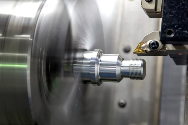
Tool selection directly affects cutting forces, chip formation, machining cycle time, and tool life. Different materials have different hardness levels, toughness, thermal conductivity, and work-hardening tendencies, so one insert grade may not be suitable for every component. When sourcing custom CNC turning services, understanding how a manufacturer matches tool materials and cutting-edge geometry to the workpiece material can help buyers evaluate its machining capabilities.
Select Insert Materials According to the Workpiece
Material properties determine the thermal and mechanical loads experienced by the cutting tool, as well as the type of wear that develops. Insert selection should consider the material grade, hardness, machining allowance, cutting speed, and production volume.
- Aluminum components: Aluminum alloys are generally easy to machine, but some grades can form built-up edges on the cutting tool. Sharp cutting edges and geometries designed for aluminum, combined with appropriate cutting speeds, can improve surface finish and dimensional stability.
- Stainless steel components: Stainless steel is relatively tough, and some grades are prone to work hardening. Inserts designed for stainless steel and suitable chipbreaker geometries can help prevent excessive rubbing and improve chip evacuation.
- Carbon steel and alloy steel components: Insert grades should be selected according to material hardness, heat-treatment condition, and cutting allowance. Roughing operations typically prioritize impact resistance and wear resistance, while finishing operations require a balance of edge sharpness, dimensional control, and surface quality.
- Copper alloy components: Machining characteristics vary considerably among copper alloys. Tool geometry should be matched to the material’s hardness and toughness to reduce burr formation, tool adhesion, and chip entanglement.
Effective insert selection should be based on the actual material grade and verified through trial machining. Relying exclusively on generic parameters or a single tooling solution may shorten tool life, destabilize surface quality, and increase the cost per part.
Match Tool Nose Radius and Geometry to Part Design
The tool nose radius, rake angle, clearance angle, and entering angle influence cutting forces, chip direction, and surface texture. A larger nose radius can improve theoretical surface roughness, but it may also increase radial cutting forces and cause vibration when machining slender shafts or thin-walled parts. A smaller nose radius can reduce certain cutting loads, but its performance must be evaluated alongside feed rate and cutting-edge strength.
For slender shafts, manufacturers should assess workpiece rigidity and consider tailstock support or a steady rest before finalizing tool geometry. Thin-walled sleeves require careful control of clamping deformation and cutting forces, sometimes making staged machining and light finishing cuts necessary. For deep grooves, narrow slots, and internal bores, tool overhang, chip clearance, and vibration risks must also be considered.
How to Adjust CNC Turning Parameters to Reduce Manufacturing Costs
Cutting speed, feed rate, and depth of cut jointly determine material removal rate, cutting temperature, tool loading, and machining time. Parameters that are too conservative may extend production cycles, while overly aggressive settings can accelerate tool wear, increase vibration, and cause dimensional deviations. Actual production parameters should be optimized according to the material, machine power, workpiece rigidity, and tool manufacturer’s recommendations rather than copied from a fixed preset.
Match Cutting Speed with Spindle Speed
Cutting speed determines the relative movement between the cutting edge and the workpiece surface. Excessively low speeds may encourage built-up edge formation or reduce productivity, while excessively high speeds can increase tool temperature and accelerate wear. Manufacturers should consult the recommended ranges for the specific material and insert grade, then validate performance through trial machining.
With constant surface speed control, the CNC system can adjust spindle speed as the workpiece diameter changes. This can improve machining conditions when turning end faces and sections with different diameters. However, a suitable maximum spindle speed limit is still necessary, particularly when machining large-diameter workpieces, using limited clamping setups, or handling components with eccentricity risks. Higher spindle speeds should only be used when the machine, fixture, and workpiece can operate safely under those conditions.
Feed Rate နှင့် Cut Depth ကို အကောင်းဆုံးဖြစ်အောင်ပြုလုပ်ခြင်း
Feed rate determines how much material the tool cuts per revolution and affects both cycle time and surface texture. A higher feed rate can shorten machining time but may increase surface roughness and cutting forces. A lower feed rate can support finer control, although under certain material and tooling conditions it may also cause rubbing, built-up material, or reduced productivity.
Depth of cut should be selected according to the machining allowance, machine rigidity, tool strength, and workpiece geometry. Roughing can use a higher material removal rate within the machine’s operating limits to remove excess material efficiently. Finishing requires a consistent and suitable allowance to prevent uneven cutting loads. For thin-walled parts, slender shafts, and small-diameter components, reducing cutting loads may provide better dimensional control than simply increasing feed speed.
During process development, manufacturers can adjust parameters one at a time. They should first verify tooling and clamping conditions, then modify cutting speed, feed rate, or depth of cut while recording dimensions, surface roughness, chip shape, and tool wear. These records help identify the actual benefits of each adjustment and reduce material waste and labor costs caused by repeated trial cuts.
How to Reduce Burrs, Chatter Marks, and Chip Evacuation Problems in CNC Turning
Burrs, chatter marks, and tangled chips are common problems that affect the appearance, dimensions, and production continuity of turned components. These defects rarely result from a single cause. Instead, they may arise from the combined effects of tool condition, workpiece rigidity, cutting parameters, coolant delivery, and toolpath design. Effective process improvement begins by identifying the defect type and then addressing its underlying cause.
Control Burr Formation and Improve Edge Quality
Burrs commonly form at end-face transitions, bore entrances, groove edges, and cutoff locations. Material toughness, cutting-edge wear, feed direction, and cutting conditions can all affect burr size. For components requiring precise assembly, burrs may interfere with positioning, increase manual deburring time, or detach during assembly and cleaning.
- Inspect cutting-edge condition: Worn tools or unsuitable edge geometry can cause material deformation and tearing. Replace or adjust tools according to actual machining conditions.
- Optimize the machining sequence: Properly arranging chamfering, cutoff, and end-face operations can reduce material pulling at edges.
- Define deburring standards: Specify acceptable edge conditions, chamfer dimensions, and sharp-edge requirements in drawings or inspection documents to ensure consistent treatment across production batches.
- Evaluate secondary finishing: For parts with strict burr requirements, select manual deburring or suitable mechanical finishing according to the material, geometry, and precision requirements. Recheck critical dimensions after processing.
Diagnose Chatter Through Clamping, Tooling, and Chip Evacuation
Chatter often appears as periodic surface patterns or waves. It may also be accompanied by unusual noise, dimensional variation, and reduced tool life. Slender shafts, thin-walled sleeves, and internal turning operations with long tool overhangs are particularly susceptible to vibration. Simply reducing spindle speed may temporarily improve the surface, but it does not always eliminate the underlying cause.
Troubleshooting should include workpiece clamping length, clamping pressure, chuck contact, tailstock support, tool overhang, and insert installation. Manufacturers should also check whether the machine, turret, or fixture has excessive movement or other abnormalities. To prevent chip entanglement, select suitable chipbreaker geometries, feed rates, and depths of cut for the material. Coolant or high-pressure cutting fluid should reach the cutting zone effectively. Proper chip evacuation reduces the risk of chips scratching finished surfaces and helps maintain continuous automated production.
How to Maintain Consistent Quality and Control Costs in CNC Turning Batch Production
Passing a single-part inspection does not guarantee stable quality throughout a production batch. As machining continues, tool wear, machine temperature changes, material batch variations, and changes in clamping conditions can gradually shift dimensions. Standardized machining procedures, inspection plans, and tool management practices help reduce batch variation and make delivery quality more predictable.
Establish Critical Dimension Inspection and Tool Life Management
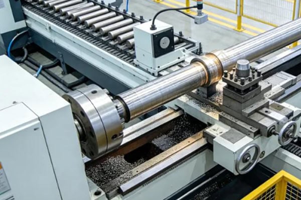
Before batch production, manufacturers should identify critical dimensions, tolerance grades, surface roughness requirements, and special inspection criteria from the engineering drawings. For critical features such as mating diameters, bore sizes, overall lengths, and concentricity, an inspection plan can include first-article inspection, in-process sampling, and final-part checks. High-precision components may also require measuring instruments suited to the specified tolerances, together with clearly defined measurement methods, environmental conditions, and acceptance criteria.
Tool life management is equally important. Manufacturers can establish tool replacement intervals and inspection rules based on material, cutting parameters, part quantity, and historical wear records. When dimensions gradually drift, they should determine whether tool compensation, parameter adjustments, or more frequent inspections are required rather than relying solely on operator experience. Maintaining machining program versions, tooling parameters, and inspection records also improves consistency when repeat orders are produced.
Choose a Custom CNC Turning Supplier with Strong Process Capabilities
Businesses outsourcing precision turned parts should evaluate more than the quoted price. They should confirm whether the supplier understands the drawing requirements, has suitable machining equipment, and can provide reliable inspection and delivery procedures. Equipment configurations, process experience, and quality control capabilities vary between suppliers, directly affecting manufacturing risk and total purchasing costs.
ပေးသွင်းသူကို အကဲဖြတ်သည့်အခါ အောက်ပါအချက်များကို ထည့်သွင်းစဉ်းစားပါ။
- Drawing and tolerance review: Can the supplier identify critical dimensions, special tolerances, surface roughness requirements, and assembly needs during quotation, while providing manufacturability recommendations when necessary?
- Material and process matching: Can the supplier select appropriate tooling, cutting strategies, and machining sequences for aluminum, stainless steel, carbon steel, and other specified materials?
- Quality inspection capabilities: Does the supplier have measuring equipment suitable for the required precision, and can it provide first-article reports, dimensional inspection records, or other agreed quality documents?
- Prototype and batch production: Can the supplier support sample validation, process adjustments, batch manufacturing, and repeat-order management while clearly defining lead times, packaging, and shipping requirements?
- Communication and change management: When drawings, materials, or delivery schedules change, can the supplier promptly confirm the impact and update the machining and inspection arrangements?
A reliable CNC turning supplier can identify process risks before production, control critical parameters during machining, and use inspection data to verify that parts meet specifications. For buyers, this structured capability helps reduce repeated revisions, rework, and delivery delays.
Practical Recommendations for CNC Turning Process Optimization
CNC turning process optimization should begin with engineering drawings, material properties, and actual production data. Tool selection, cutting parameters, clamping methods, chip evacuation, and quality inspection should be integrated into a unified manufacturing process. For simple parts produced in large quantities, manufacturers can prioritize cycle time and tool life. For thin-walled components, slender shafts, and high-precision mating parts, greater attention should be given to rigidity, thermal stability, and critical dimension inspection.
When introducing a new component, manufacturers can begin with drawing review and material verification, followed by trial machining and first-article inspection. Once the cutting parameters are validated, they should be documented in standardized work instructions. During batch production, process performance can be evaluated through dimensional trends, tool consumption, surface quality, and defect rates. When materials, equipment, or design requirements change, the affected operations should be revalidated instead of automatically reusing previous parameters.
For customers requiring custom precision components, partnering with a CNC machining supplier that provides process evaluation, manufacturing, and quality inspection can help balance machining accuracy, delivery time, and production costs. A stable process system not only improves the acceptance rate of each production batch but also creates a reliable foundation for future repeat orders.