CNC turning is widely used in the manufacturing of mechanical equipment, automotive components, automation systems, industrial connectors, and precision instruments. Thread quality directly affects assembly efficiency, connection strength, and long-term operating stability. For businesses purchasing precision-turned components in bulk, problems such as pitch deviations, incomplete thread profiles, rough thread surfaces, or excessively tight fits can increase rework costs and disrupt assembly operations. Selecting appropriate threading processes, cutting tools, and inspection methods helps improve dimensional consistency and meet the accuracy requirements of different applications.
What Affects CNC Thread Turning Accuracy?
CNC thread turning requires coordinated machine movement, spindle speed, synchronized feed, tool geometry, and workpiece clamping. Even when the external thread diameter meets the drawing requirements, deviations in pitch, thread profile angle, or pitch diameter can cause poor thread engagement. Confirming thread specifications, accuracy grades, and inspection requirements before machining helps manufacturers develop a more stable production process.
Thread Parameters and Engineering Drawings
Thread machining requires accurate identification of metric threads, imperial threads, pipe threads, and other specialized thread types. Different thread standards have different profiles, pitches, and dimensional requirements. Machining parameters should not be determined solely by the external thread diameter.
- Thread pitch: Pitch determines the axial distance between adjacent thread crests. An incorrect pitch setting directly affects thread engagement. Even if the external diameter is correct, the component may not assemble properly.
- Thread pitch diameter: The pitch diameter is an important parameter for evaluating thread fit. It affects clearance, contact conditions, and resistance during assembly.
- Thread profile angle and depth: The cutting tool profile must match the specified thread standard. Deviations in the profile angle, insufficient cutting depth, or excessive depth can compromise connection performance.
- Tolerance grade: Designers should select an appropriate tolerance grade according to the fit type, load requirements, and operating environment. Excessively tight tolerances may increase manufacturing costs unnecessarily.
Before batch production, manufacturers should review the thread designation, effective thread length, relief grooves, chamfers, and fit tolerances shown in the engineering drawings. For non-standard threads, complete profile parameters and inspection methods must also be confirmed to reduce programming errors and subsequent assembly problems.
Desgaste da ferramenta e condições de corte
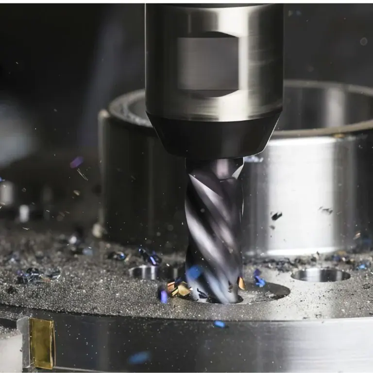
The condition of a threading tool directly affects profile accuracy and surface quality. Extended tool use, edge chipping, or uneven wear can alter the thread profile. When machining materials such as stainless steel and alloy steel, tool wear and cutting heat can further affect dimensional stability.
Tool selection should depend on the workpiece material, thread specifications, cutting method, and production volume. Carbide threading inserts are suitable for many conventional metal machining applications. Specialized materials or complex threads may require parameter verification based on the tool manufacturer’s recommendations. Secure tool installation, accurate tool-tip positioning, and regular cutting-edge inspections help reduce burrs, chatter marks, and profile deviations.
Machine Synchronization and Workpiece Clamping
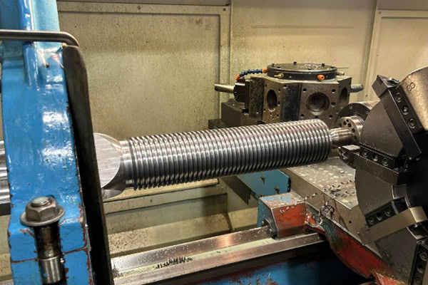
CNC thread turning depends on precise synchronization between spindle rotation and the axial movement of the cutting tool. Transmission errors, abnormal spindle conditions, or incorrect threading program settings can cause pitch deviations, crossed threads, or periodic surface marks.
Workpiece clamping is equally important. Long, slender shaft components may bend or vibrate during cutting if they lack sufficient support. Thin-walled components can deform when excessive clamping force is applied. Machinists should select suitable fixtures according to workpiece length, diameter, material stiffness, and thread position. A tailstock or other auxiliary support may be necessary for certain components. Stable clamping helps maintain the correct cutting path and improves consistency during repeated production.
How to Improve CNC Thread Turning Quality
Improving thread accuracy requires more than an advanced machine. It also depends on an appropriate machining program, stable cutting parameters, and standardized process management. For precision threaded components that require long-term supply, a repeatable manufacturing process is more effective at controlling batch variations than relying solely on operator experience.
Optimize the Thread Turning Program
Threading programs must accurately define the pitch, thread length, approach position, retract position, and cutting depth. Thread-cycle commands may vary between CNC systems, so programmers should verify the settings against the machine’s operating instructions and the actual workpiece geometry.
- Arrange cutting passes appropriately: For threads requiring substantial material removal, multiple passes can distribute the cutting load and help prevent excessive tool pressure, vibration, or profile damage.
- Control the final cutting passes: During finishing, maintain stable cutting conditions. Unnecessary parameter changes can affect the pitch diameter and surface quality.
- Check the tool retract path: Blind-hole threads, threads near shoulders, and long threads require sufficient retract space to prevent tool collisions and damage to the effective thread profile.
- Verify the program before production: Before machining the first part, check the program parameters, tool offsets, and spindle synchronization. Where practical, use simulation, a dry run, or a controlled trial cut to verify the tool path.
Standardized program settings help reduce the risk of crossed threads, dimensional deviations, and tool collisions. For repeat orders, saving verified programs and machining parameters can also shorten setup time for subsequent production runs.
Select Suitable Cutting Parameters
Cutting speed, synchronized feed, cutting depth, and cooling conditions jointly affect thread machining stability. Excessive cutting speed can accelerate tool wear and heat accumulation, while inappropriate parameters may cause vibration or uneven thread surfaces. Actual settings should be verified through trial machining based on material hardness, insert grade, thread dimensions, and machine capability.
- Match the cutting speed to the application: Select spindle speed according to the workpiece material and the tool manufacturer’s recommended range. Avoid prioritizing production speed at the expense of tool life and dimensional stability.
- Distribute the cutting allowance: Allocate material removal across an appropriate number of passes to reduce the load on each pass, particularly when machining large-pitch or deep threads.
- Improve chip evacuation: Materials that produce long chips require effective chip removal. This helps prevent chips from wrapping around the tool or scratching finished thread surfaces.
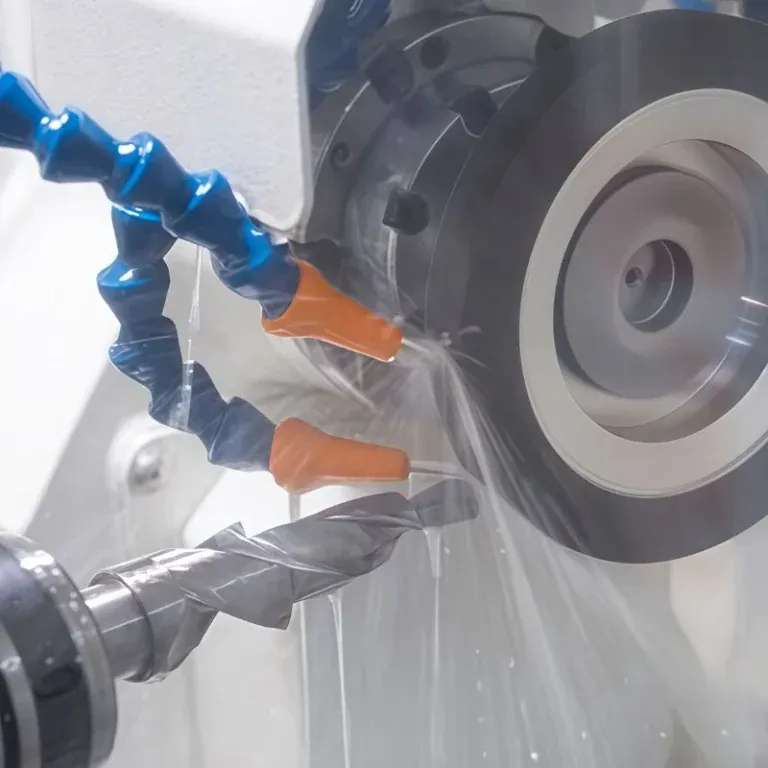
- Maintain stable cooling conditions: Use a suitable cutting fluid or cooling method based on the material and tooling requirements. Proper cooling helps control heat accumulation and maintain stable cutting conditions.
Parameter optimization should be based on actual inspection data. By recording first-piece dimensions, tool condition, and batch inspection results, manufacturers can gradually establish stable machining parameters for specific materials and thread specifications.
Strengthen Tool Management and Process Control
Tool management directly affects the consistency of batch thread production. When manufacturing large quantities of components, waiting until visible quality problems appear before replacing a tool may allow dimensional deviations to develop in previously machined parts. Defined inspection and replacement schedules help reduce this risk.
During production, inspection intervals should be determined according to machining volume, material characteristics, and tool wear. Operators should monitor thread surfaces for tearing, burrs, chatter marks, and local damage. If abnormalities appear, they should promptly inspect the cutting insert, clamping condition, and program parameters. For critical components, manufacturers can also maintain records of tool changes, program versions, production batches, and inspection results to support quality traceability.
How to Inspect and Accept Precision CNC Threaded Parts
Thread quality acceptance should be based on engineering drawings, applicable thread standards, and the component’s intended application. Measuring only the external thread diameter cannot fully establish whether a thread will fit correctly. Pitch, pitch diameter, profile geometry, and effective thread length can also affect assembly performance. A suitable inspection process helps manufacturers and buyers verify compliance with technical requirements more accurately.

Use Professional Thread Gauges to Check Dimensions
Common thread inspection tools include thread ring gauges, thread plug gauges, pitch gauges, and measuring equipment suitable for the specified dimensions. Each tool serves a different purpose and should be selected according to the thread type and accuracy requirements.
- Thread ring gauges: These are primarily used to check the fit of external threads and should match the specified thread size and tolerance grade.
- Thread plug gauges: These are used to verify whether internal threads meet the required go/no-go conditions. They are suitable for rapid inspection of batch-produced components.
- Pitch gauges: These help verify whether the thread pitch matches the design specification, but they cannot replace a complete thread accuracy inspection.
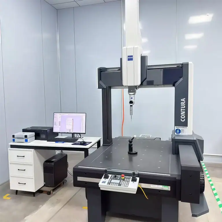
- Precision measuring equipment: When drawings impose strict requirements for pitch diameter, profile geometry, or specialized thread contours, suitable professional equipment can be used for more detailed measurements.
Before inspection, confirm the gauge specification, accuracy grade, and calibration status. Follow the applicable inspection standards and operating procedures. For critical assembly components, combining go/no-go gauge testing with appropriate dimensional measurements helps prevent important defects from being overlooked.
Perform First-Article Inspection and Batch Sampling
First-article inspection can identify problems with programs, cutting tools, or workholding before full-scale production begins. After the first part passes inspection, manufacturers should establish a batch inspection plan based on order quantity, component risk, and customer quality requirements. This helps detect dimensional drift as machine operating time increases.
During production, particular attention should be paid to thread engagement, effective thread length, burrs at the ends, and visible surface defects. For high-precision components, safety-critical applications, or parts subject to customer-mandated 100% inspection, the specified inspection requirements must be followed. Routine sampling should not replace a required full inspection.
Choose a CNC Machining Supplier with Strong Qualite controle
When purchasing precision threaded components, buyers should evaluate more than price and delivery time. They should also confirm whether the supplier has suitable turning equipment, threading tools, inspection gauges, and quality management procedures. A reliable machining supplier can review drawings before production, control program and tool conditions during machining, and provide dimensional inspection records according to order requirements.
For long-term purchasing projects, provide complete two-dimensional drawings, material grades, thread specifications, tolerance requirements, surface finishing details, and order quantities during quotation. For specialized threads or components with strict fit requirements, consider producing and validating samples before approving batch production. Clearly defined technical specifications, inspection standards, and delivery documentation help reduce communication errors and improve supply chain reliability.
The quality of CNC thread turning depends on the coordination of engineering design, machine synchronization, tool condition, cutting parameters, and inspection procedures. By confirming thread specifications before production, controlling cutting and clamping conditions during machining, and conducting first-article and batch inspections with suitable gauges, manufacturers can more effectively reduce dimensional deviations, assembly difficulties, and rework costs. For customers requiring customized precision threaded components, choosing a CNC machining supplier with stable manufacturing capabilities and comprehensive quality inspection procedures helps ensure that delivered parts meet design requirements.