
Plain milling is a milling process used to machine broad, flat surfaces by removing material with the peripheral cutting edges of a rotating cutter. It is commonly performed on a horizontal milling machine, where a cylindrical cutter is mounted on an arbor and the workpiece is fed beneath the rotating tool. The process is valued for stable stock removal, simple tooling, and efficient preparation of flat surfaces before further cnc milling operations.
This guide explains plain milling, including its process, cutters, machine setup, materials, advantages, limitations, common defects, and practical applications.
प्लेन मिलिंग क्या है?
Plain milling is a milling operation that removes material from a flat surface using the peripheral teeth of a cylindrical cutter. In this process, the cutter axis is generally parallel to the machined surface, and the workpiece moves past the rotating cutter to create a flat, level, or thickness-controlled surface. It is mainly used for broad surface machining, stock reduction, and preparation of reference faces before other machining operations.
The milling definition covers many processes where a rotating cutter removes material from a workpiece. Plain milling is a specific type of milling focused on flat surface generation. Unlike end milling, which often machines pockets, slots, profiles, and contours, plain milling is mainly used when the goal is to remove material from a wide, simple surface.
Plain milling is often associated with slab milling and peripheral milling because the cutting action takes place on the outside circumference of the cutter. In many shop environments, these terms may overlap. However, the important manufacturing point is not the terminology alone, but the tool orientation, cutter engagement, surface requirement, and machining purpose.
| अवधि | अर्थ | विशिष्ट उपयोग |
| सादा मिलिंग | Flat surface machining with a peripheral cutter | Broad surfaces and stock removal |
| स्लैब मिलिंग | Often used as another name for plain milling | Wide flat surfaces |
| परिधीय मिलिंग | Describes cutting with the cutter circumference | General outside-edge cutter engagement |
| फेस मिलिंग | Cutting mainly with the face of the cutter | Finishing top surfaces |
| अंत मिलिंग | Cutting with end and side edges of an end mill | Slots, pockets, profiles, and contours |
Purpose of Plain Milling in Manufacturing
The main purpose of plain milling is to create a flat surface efficiently and consistently. This can be useful when a raw block, plate, casting, or forged workpiece needs to be leveled before more precise machining. A stable plain milling operation can remove uneven stock, reduce material thickness, and create a dependable reference surface for later operations.
For example, a base plate may need one flat side before holes, pockets, slots, or mounting features are machined. If the first surface is not flat enough, later features may inherit alignment errors. Plain milling helps create a controlled starting surface, especially when the part is large, simple, and requires predictable stock removal.
Plain Milling, Slab Milling, and Peripheral Milling
Plain milling and slab milling are often used very closely because both refer to machining a flat surface with the outside surface of a cylindrical cutter. Slab milling usually emphasizes a wide cutter removing material across a broad workpiece surface, while plain milling is a more general name for the operation.
Peripheral milling describes the cutting mechanics rather than only one specific operation. In peripheral cutting, the teeth around the outside of the cutter do most of the material removal. This is why plain milling can be understood as one important example of peripheral milling.
How Does The Plain Milling Process Work?
The plain milling process works by clamping the workpiece securely, mounting a suitable plain milling cutter on the machine arbor, setting the cutting speed, feed rate, and depth of cut, and feeding the workpiece under the rotating cutter to remove material from a flat surface. The quality of the result depends on machine rigidity, workholding stability, cutter selection, cutting parameters, chip evacuation, and inspection control.
Although the plain milling operation appears straightforward, the actual process requires careful control. If the cutter is not aligned, the arbor is not rigid, or the workpiece is poorly clamped, the surface may show vibration marks, uneven thickness, poor finish, or dimensional variation. A correct setup is therefore essential before the cutter ever touches the material.
In CNC milling, the machine can repeat the programmed feed and depth accurately, but it cannot automatically correct weak fixturing, worn cutters, unstable chip evacuation, or poor parameter selection. This is why plain milling should be treated as a controlled machining process, not simply a basic flat cut.
| स्टेप | क्या होता है | यह क्यों मायने रखता है |
| वर्कपीस सेटअप | The part is clamped on the table or fixture | Prevents movement and reduces vibration |
| कटर चयन | A plain milling cutter is selected and mounted | Controls cutting force, finish, and tool life |
| पैमाना सेटिंग | Speed, feed, and depth of cut are chosen | Balances productivity and surface quality |
| Trial or first pass | The first cut confirms stability | Helps detect chatter or setup problems early |
| Main cutting pass | Material is removed across the surface | Produces the required flat area or thickness |
| फिनिशिंग पास | A lighter pass may be used | Improves surface finish and dimensional control |
| निरीक्षण | Flatness, thickness, and finish are checked | Confirms the part meets requirements |
वर्कपीस सेटअप और फिक्सचरिंग
Workpiece setup is the foundation of plain milling. The part must be supported and clamped firmly enough to resist cutting forces, but not so tightly that clamping distortion changes the final shape. This is especially important for long plates, thin sections, and large flat workpieces that can bend under pressure.
Common workholding methods include vises, clamps, step blocks, fixture plates, parallels, angle plates, and custom fixtures. The correct choice depends on part size, stiffness, surface requirement, and cutting force. A stable fixture helps reduce chatter and keeps the machined surface consistent from one pass to the next.
Cutter Selection and Arbor Setup
The cutter must match the workpiece material, surface width, stock removal target, machine rigidity, and required finish. In traditional plain milling, the cutter is mounted on an arbor. The arbor and support system must be rigid because plain milling can generate significant radial cutting forces.
A weak arbor setup can cause vibration, runout, or cutter deflection. This affects surface finish and flatness. Before machining, the cutter should be mounted securely, the arbor should be properly supported, and the tool condition should be checked for wear, chipped teeth, or uneven cutting edges.
काटने की गति, फ़ीड दर और काटने की गहराई
Cutting speed controls how fast the cutting edge moves against the material. Feed rate controls how quickly the workpiece advances under the cutter. Depth of cut controls how much material is removed in each pass. These three parameters must work together.
A deep cut and high feed can improve productivity, but they also increase cutting force and vibration risk. A light cut can improve surface finish, but it may increase cycle time. For roughing, the goal is efficient stock removal. For finishing, the goal is better surface condition and dimensional control.
पारंपरिक मिलिंग बनाम क्लाइम्ब मिलिंग
Plain milling can use conventional milling or climb milling. In conventional milling, the cutter rotation opposes the feed direction at the cutting zone. In climb milling, the cutter rotation moves with the feed direction. Each method affects cutting load, surface finish, tool wear, and machine stability differently.
Climb milling can produce better surface finish and lower cutting force in rigid machines, but it requires good machine control and minimal backlash. Conventional milling may be safer on older or less rigid machines. The choice should depend on machine condition, workholding, material, and required finish.
What Machines Are Used For Plain Milling?
Plain milling is most commonly performed on a horizontal milling machine because the spindle, arbor, and cutter arrangement are suitable for wide peripheral cutting. A vertical mill can machine flat surfaces, but traditional plain milling is more closely related to horizontal setups, where a cylindrical cutter removes material across a broad workpiece surface with strong arbor support and stable cutting engagement.
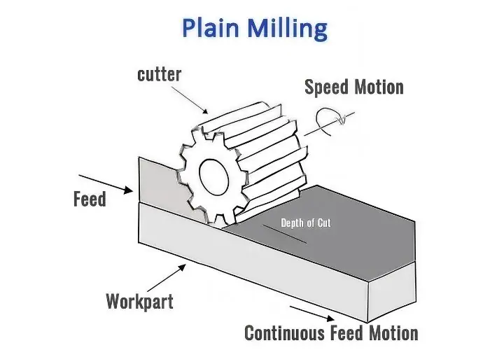
A horizontal milling machine is often preferred for plain milling because it supports arbor-mounted cutters and can handle wider tools. This arrangement is useful for flat plates, machine bases, structural parts, and workpieces requiring steady material removal across a large surface.
Modern cnc milling shops may use different machines depending on the part geometry. A horizontal mill, vertical mill, or CNC machining center may be selected based on machine availability, part size, tolerance, surface finish, and production volume. The machine should be chosen according to process stability rather than machine name alone.
| मशीन की तरह | Suitability for Plain Milling | मुख्य लाभ | मुख्य सीमा |
| क्षैतिज मिलिंग मशीन | बहुत उपयुक्त | Strong arbor support and wide cutter capacity | Less flexible for complex pockets |
| ऊर्ध्वाधर मिल | Limited for traditional plain milling | Flexible for general CNC machining | Better suited to face milling and end milling |
| सीएनसी क्षैतिज मशीनिंग केंद्र | Suitable for controlled production | Repeatability and automation | उच्च उपकरण लागत |
| मैनुअल मिलिंग मशीन | Suitable for simple operations | Flexible and accessible | Operator skill strongly affects consistency |
क्षैतिज मिलिंग मशीन
A horizontal milling machine is the classic machine for plain milling. Its spindle is oriented horizontally, and the cutter is mounted on an arbor. The workpiece moves along the table while the rotating cutter removes material from the surface.
This machine type is useful when the cutter must cover a wide surface and remove material steadily. The arbor support helps improve rigidity, which is important for heavy stock removal and stable surface generation.
Vertical Mill and Plain Milling Limitations
A vertical mill can machine flat surfaces, but it usually does so through face milling or end milling rather than traditional plain milling. Its spindle is vertical, so the cutter axis is usually perpendicular to the work surface. This makes it more suitable for pockets, slots, holes, contours, and top-face finishing.
A vertical mill is still important in modern CNC machining because of its flexibility. However, when the goal is a classic plain milling operation using a wide arbor-mounted cutter, a horizontal milling machine is usually more appropriate.
Arbor Support, Cutter Mounting, and Machine Rigidity
Arbor support, cutter mounting, and machine rigidity directly affect plain milling quality. If the cutter is not supported properly, vibration and deflection can occur. This can create chatter marks, rough surfaces, inaccurate thickness, and inconsistent flatness.
A stable setup requires proper cutter spacing, secure arbor support, correct tool mounting, and suitable machine condition. When the machine and tooling system are rigid, the plain milling process becomes more predictable and repeatable.
What Are Plain Milling Cutters?
Plain milling cutters are cylindrical cutters with teeth around their outer circumference, designed to remove material through peripheral cutting action. Their diameter, width, tooth form, helix angle, cutter material, coating, and duty level determine how much material they can remove, how smooth the surface becomes, and how stable the cutting process remains during machining.
The cutter is a major factor in plain milling performance. A cutter used for roughing must have enough strength and chip space to remove larger amounts of material. A cutter used for finishing should provide smoother cutting engagement and better surface quality. Choosing the wrong cutter can cause chatter, short tool life, poor finish, or unstable chip evacuation.
Plain milling cutters are often categorized by tooth form, cutting duty, and application. Light-duty cutters are generally used for lighter cuts and better finish, while heavy-duty cutters are designed for more aggressive material removal. Straight-tooth and helical-tooth cutters also behave differently during cutting.
| कटर प्रकार | सबसे अच्छा है | मुख्य लाभ | मुख्य सीमा |
| Light-duty plain milling cutter | Light cuts and finishing | बेहतर सतह खत्म | Not ideal for heavy stock removal |
| Heavy-duty plain milling cutter | Roughing and high material removal | Strong cutting capacity | May leave rougher finish |
| Straight-tooth cutter | Simple general cutting | सरल संरचना | More vibration risk |
| Helical-tooth cutter | Stable production cutting | Smoother cutting engagement | Requires proper setup |
| Wide plain milling cutter | बड़ी सपाट सतहें | Efficient surface coverage | उच्चतर काटने वाला बल |
| Plain milling cutter diagram | Tool education and process planning | Helps explain cutter geometry | Not a tool type itself |
Plain Milling Cutter Structure and Geometry
A plain milling cutter has a cylindrical body with cutting teeth arranged around the outside. The cutter may vary in width, diameter, tooth count, helix angle, and material. These design details control how the cutter engages the workpiece and removes chips.
Cutter geometry affects cutting force, chip formation, surface finish, and tool life. A stronger tooth design may support heavier cuts, while finer teeth may improve surface quality. For stable machining, the cutter geometry should match the material and operation.
Straight-Tooth vs. Helical-Tooth Cutters
Straight-tooth cutters have teeth parallel to the cutter axis. They are simple and useful for general work, but the cutting engagement can be more interrupted. This may increase vibration, especially in wider cuts or less rigid setups.
Helical-tooth cutters have angled teeth that enter the material more gradually. This smoother engagement can reduce vibration, improve surface finish, and distribute cutting load more evenly. Helical cutters are often preferred when stability and finish matter.
Light-Duty Plain Milling Cutter
A light-duty plain milling cutter is used for lighter material removal, finishing passes, or smaller machines. It is useful when the part requires better surface quality rather than maximum stock removal. These cutters usually create lower cutting forces and can help improve dimensional control.
Light-duty cutters are suitable for aluminum, mild steel, and other materials when the operation does not require aggressive cutting. They may not be strong enough for deep roughing cuts or heavy-duty industrial stock removal.
Heavy-Duty Plain Milling Cutter
A heavy-duty plain milling cutter is designed for roughing and larger material removal. It typically has stronger cutting teeth and more chip space, allowing it to handle higher cutting loads. This makes it useful for large workpieces, structural parts, and early-stage stock removal.
The tradeoff is surface finish. Heavy-duty cutters may leave a rougher surface than finishing cutters, especially at aggressive feed and depth settings. In many cases, a finishing pass is still needed after rough plain milling.
How to Choose the Right Plain Milling Cutter?
The right cutter should be selected according to workpiece material, surface width, stock removal amount, machine rigidity, arbor support, surface finish target, and production volume. A cutter that works well for aluminum may not be the best choice for stainless steel or cast iron.
A practical cutter selection process includes:
- Identify whether the operation is roughing, semi-finishing, or finishing.
- Match cutter width to the surface and machine capacity.
- Choose tooth geometry according to material and chip formation.
- Check whether the machine and arbor can support the cutting force.
- Consider tool life, surface finish, and cycle time together.
- Avoid overly aggressive cutters if rigidity is limited.
What Are The Key Parameters In Plain Milling?
The key parameters in plain milling include cutting speed, feed rate, depth of cut, width of cut, cutter engagement, tool geometry, coolant use, and the required tolerance or surface finish. These parameters control material removal rate, cutting force, heat generation, tool wear, chip formation, surface quality, and dimensional accuracy.
Plain milling may look simple, but changing one parameter can affect the entire process. Increasing depth of cut improves productivity but raises cutting force. Increasing feed may reduce cycle time but can worsen finish. Increasing speed may improve cutting action but can increase heat and tool wear.
The best parameter combination depends on the material, cutter, machine, fixture, and final requirement. Roughing should focus on efficient material removal without instability. Finishing should focus on surface quality, flatness, and dimensional control.
| प्राचल | यह क्या नियंत्रित करता है | If Too Aggressive | If Too Conservative |
| काटने गति | Heat and cutting action | Tool wear, burning, overheating | कम उत्पादकता |
| फ़ीड दर | Chip load and cycle time | Rough finish, high force | Rubbing, low efficiency |
| कटौती की गहराई | Material removed per pass | बकबक, विक्षेपण | Too many passes |
| Width of cut | Cutter engagement | High cutting load | कम उत्पादकता |
| Coolant/lubrication | Heat and chip flow | Excess mess if misused | Heat, wear, chip packing |
| Cutter geometry | Chip formation and stability | Wrong tool can chatter | Tool may cut inefficiently |
| workholding | भाग स्थिरता | Distortion if over-clamped | Movement if under-clamped |
काटने की गति, फ़ीड दर और काटने की गहराई
Cutting speed is the surface speed of the cutter against the material. Feed rate is how fast the workpiece moves past the cutter. Depth of cut is how much material is removed vertically in each pass. These settings must be balanced to avoid tool wear, chatter, and poor finish.
For roughing, higher material removal may be acceptable if the setup is rigid. For finishing, a lighter and more stable pass is usually better. The same cutting strategy should not be applied to every material or surface requirement.
Width of Cut and Tool Engagement
Width of cut determines how much of the cutter engages the workpiece across the surface. Plain milling often involves wide engagement, which can improve productivity but also increase cutting load. If the machine or fixture cannot support this load, vibration may occur.
Tool engagement should be chosen according to cutter size, material, and rigidity. Stable engagement produces consistent chip formation and surface finish. Unstable engagement produces noise, chatter, tool wear, and dimensional variation.
सहनशीलता और आयामी नियंत्रण
Plain milling can produce consistent flat surfaces when the machine, cutter, and setup are stable. However, tolerance depends on many factors, including machine accuracy, arbor rigidity, workholding, cutter condition, material movement, and inspection method.
For precision components, plain milling may be used for roughing or reference surface preparation, followed by finishing operations. When tight flatness or thickness is required, staged machining and careful inspection may be needed.
Surface Finish and Flatness Control
Surface finish is influenced by cutter sharpness, tooth geometry, feed rate, cutting speed, vibration, and chip evacuation. Flatness is influenced by workpiece support, clamping method, material stress, and cutting strategy. A good-looking surface is not always flat, and a flat surface may still need finish improvement.
For large plates and structural components, flatness control often requires more than one pass. Roughing can remove most material, while a lighter finishing pass can improve surface condition and dimensional stability.
शीतलक और स्नेहन
Coolant and lubrication help reduce heat, control friction, improve chip evacuation, and extend tool life. Their importance depends on the material and cutting condition. Aluminum may need chip evacuation support, while stainless steel may require stronger heat control.
Poor coolant management can cause chip recutting, surface damage, overheating, or tool wear. However, coolant should support the cutting process rather than simply be added in large volume without purpose.
What Materials Are Suitable For Plain Milling?
Plain milling is suitable for many engineering materials, including aluminum, steel, stainless steel, cast iron, copper alloys, and some engineering plastics. The material’s hardness, ductility, toughness, thermal behavior, chip formation, and internal stress determine cutter selection, cutting parameters, coolant strategy, and the likelihood of burrs, vibration, or tool wear.
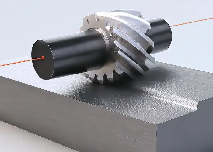
Material behavior strongly affects plain milling results. Aluminum is usually easier to cut but can produce built-up edge if the tool is dull. Steel can require higher cutting force. Stainless steel may work-harden. Cast iron can be stable but abrasive. Plastics can deform under heat or clamping pressure.
Because materials respond differently, the same plain milling cutter and parameters should not be copied from one job to another without review. A good process adapts cutter geometry, speed, feed, depth of cut, and coolant to the specific material.
| सामग्री | मशीनिंग व्यवहार | मुख्य सरोकार | व्यावहारिक युक्ति |
| एल्युमीनियम | Easy to machine, high chip flow | Burrs and built-up edge | तेज़ धार वाले औजारों का प्रयोग करें और चिप्स को अच्छी तरह से बाहर निकालें। |
| स्टील | उच्चतर काटने वाला बल | औजारों का घिसाव और गर्मी | Use rigid setup and suitable parameters |
| स्टेनलेस स्टील | Tough and may work-harden | Heat and cutter wear | Avoid rubbing and use proper coolant |
| कच्चा लोहा | Stable but abrasive | Tool wear and dust/chips | Use suitable tool material |
| तांबे की मिश्र धातु | Ductile and sometimes gummy | Smearing and burrs | Use sharp geometry and controlled feed |
| इंजीनियरिंग प्लास्टिक | Heat-sensitive and flexible | Deformation and melting | Use sharp tools and light cutting loads |
एल्युमिनियम और अलौह धातुएँ
Aluminum is commonly plain milled because it is lightweight, machinable, and widely used in plates, housings, brackets, and automation parts. It can be machined efficiently, but soft aluminum alloys may form burrs or built-up edge if the cutter is not sharp or chips are not cleared properly.
Copper and other non-ferrous metals can also be plain milled, but they may require different cutter geometry. The goal is to shear the material cleanly rather than smear it across the surface. Tool sharpness and chip evacuation are important.
स्टील और स्टेनलेस स्टील
Steel and stainless steel need greater attention to cutting force, rigidity, and tool wear. They are generally less forgiving than aluminum, especially when the setup is weak or the cutter is worn. Poor cutting conditions can increase heat and reduce tool life.
Stainless steel is more challenging because it can work-harden if the cutter rubs instead of cutting cleanly. Proper feed, sharp tooling, coolant, and rigid workholding help maintain a stable process.
Cast Iron and Structural Materials
Cast iron can be suitable for plain milling because it often breaks into small chips and has good dimensional stability. However, some cast irons are abrasive and can wear cutters faster. Tool material and dust control should be considered.
Structural materials used in machinery, construction equipment, and industrial components often require broad surface preparation. Plain milling can be useful when these parts need flat mounting faces or thickness control before additional machining.
How Material Properties Affect Cutter Selection
Material properties affect cutter selection because each material creates different cutting forces and chip behavior. A cutter designed for light aluminum finishing may not be strong enough for heavy steel stock removal. A roughing cutter may remove material quickly but may not meet a fine finish requirement.
Cutter selection should consider:
- सामग्री की कठोरता और मजबूती
- Chip type and chip evacuation
- आवश्यक सतह फिनिश
- Stock removal amount
- उपकरण घिसाव प्रतिरोध
- Machine and arbor rigidity
- Coolant or lubrication requirements
What Are The Advantages And Limitations Of Plain Milling?
Plain milling offers efficient flat-surface machining, stable material removal, simple tooling, and good suitability for broad workpiece surfaces, but it is limited when parts require complex contours, pockets, deep cavities, detailed profiles, or very fine surface finishes. It is best used when the machining goal is simple, flat, and stable material removal.
The biggest advantage of plain milling is its productivity on wide flat surfaces. A suitable cutter can remove material across a broad area, making the process useful for stock preparation, surface leveling, and base surface machining. The setup can be simple when the part geometry is straightforward.
The limitations come from geometry and flexibility. Plain milling is not the best option for detailed 3D features, internal cavities, narrow slots, or complex part profiles. In those situations, end milling, face milling, slot milling, or multi-axis सीएनसी मिलिंग अधिक उपयुक्त हो सकता है.
| पहलू | फायदे | सीमाओं |
| सतह की मशीनिंग | Efficient for wide flat surfaces | जटिल ज्यामिति के लिए सीमित |
| टूलींग | Uses standard cutter types | Requires correct arbor/cutter setup |
| उत्पादकता | Good for heavy stock removal | May need finishing pass |
| मशीन सेट अप | Stable on horizontal machines | Less convenient on vertical setups |
| लागत | Cost-effective for simple surfaces | Less efficient if many setups are needed |
| शुद्धता | Can support controlled flatness | Sensitive to clamping and vibration |
Advantages of Plain Milling
Plain milling can remove material efficiently from wide surfaces, making it useful for roughing and surface preparation. It can also provide stable cutting when the machine, arbor, cutter, and fixture are rigid. This makes it valuable for plates, base components, structural parts, and large rectangular workpieces.
The tooling is also relatively simple compared with more complex machining operations. When the geometry fits the process, plain milling can reduce unnecessary toolpath complexity and provide predictable stock removal.
Disadvantages of Plain Milling
Plain milling is not ideal for complex geometries. It cannot easily machine pockets, curved profiles, fine details, or deep internal shapes. It may also produce a rougher finish during heavy stock removal, requiring a secondary finishing operation.
Another limitation is equipment. Traditional plain milling is most effective on horizontal milling machines. If a shop mainly uses vertical machining centers, face milling or end milling may be more practical.
When to Use Plain Milling?
Plain milling should be used when the part needs a wide, flat surface machined efficiently. It is suitable for base plates, stock preparation, reference surfaces, structural parts, and large workpieces with simple geometry.
It is also useful when the process can remove material in a stable and repeatable way without requiring complex toolpaths. If the feature is broad, flat, and accessible, plain milling can be a practical choice.
When Not to Use Plain Milling?
Plain milling should not be used when the part requires complex pockets, internal cavities, curved contours, narrow slots, or detailed profiles. These features are better suited to end milling, side milling, slot milling, or multi-axis machining.
It may also be unsuitable when a very fine surface finish is required directly from the operation. In that case, face milling, grinding, or another finishing method may be used after plain milling.
How Does Plain Milling Compare With Other Milling Operations?
Plain milling differs from other milling operations in cutter orientation, cutting-edge engagement, target surface, and application. Plain milling is mainly used for broad flat surfaces, while face milling focuses on top surface finishing, end milling handles pockets and profiles, side milling cuts vertical side surfaces, straddle milling machines two parallel faces, and slot milling creates grooves or channels.
Understanding these differences helps engineers choose the correct process. A part may require more than one milling operation. For example, plain milling may prepare a large flat surface, face milling may improve final finish, end milling may create pockets, and drilling may produce holes.
The best milling method depends on geometry, tolerance, material, surface finish, machine availability, and cost. No single milling operation is best for every feature.
| आपरेशन | Main Cutting Action | सबसे अच्छा है | Difference From Plain Milling |
| सादा मिलिंग | Peripheral cutter teeth | Wide flat surfaces | Main process for broad surface stock removal |
| फेस मिलिंग | Cutter face and edges | Top face finishing | Often gives better surface finish |
| अंत मिलिंग | End and side cutting edges | Pockets, slots, profiles | More flexible for complex geometry |
| साइड मिलिंग | Side cutter engagement | Vertical side faces | Focuses on side surfaces |
| स्ट्रैडल मिलिंग | Two side cutters | Two parallel faces | Machines both sides at once |
| स्लॉट मिलिंग | Slotting cutter or end mill | खांचे और चैनल | Cuts into the workpiece rather than leveling broad surfaces |
| स्लैब मिलिंग | Wide peripheral cutter | Broad flat surfaces | Often treated as the same as plain milling |
Plain Milling vs. Face Milling
Plain milling uses the peripheral cutting edges of the cutter, and the cutter axis is generally parallel to the work surface. Face milling uses the cutter face, and the tool axis is usually perpendicular to the machined surface.
Face milling is often preferred for achieving a smoother top surface, while plain milling is effective for broad material removal. In some process plans, plain milling may be used first, followed by face milling for final finish.
Plain Milling vs. End Milling
End milling uses an end mill that can cut with both the end and side of the tool. This makes end milling more flexible for pockets, slots, profiles, and complex 2D or 3D features.
Plain milling is less flexible but can be efficient for wide, flat surfaces. If the part requires complex shape generation, end milling is usually more suitable. If the part requires surface leveling across a broad area, plain milling may be more efficient.
Plain Milling vs. Side Milling
Side milling uses a cutter to machine side surfaces or vertical faces. It is useful when the goal is to create or finish a side wall. Plain milling focuses on flat surface machining with a broad peripheral cut.
Both operations may use peripheral cutting, but the target surface is different. Plain milling works across a broad top or flat surface, while side milling works along the side of the workpiece.
Plain Milling vs. Straddle Milling
Straddle milling uses two cutters mounted on the same arbor to machine two parallel surfaces at the same time. It is useful when both sides of a feature need to be machined with controlled spacing.
Plain milling typically machines one broad surface. Straddle milling is more specialized and is used when parallel side faces must be produced efficiently.
Plain Milling vs. Slot Milling
Slot milling creates grooves, channels, or slots. It cuts into the workpiece rather than simply leveling a broad surface. Tools may include slotting cutters or end mills.
Plain milling is used for flat surface generation and stock removal. If the feature is a groove or channel, slot milling is usually the correct choice.
What Are Common Problems In Plain Milling And How Can You Fix Them?
Common problems in plain milling include chatter, vibration, poor surface finish, fast tool wear, chip packing, burr formation, overheating, and inaccurate flatness or thickness. These problems usually come from weak workholding, poor cutter selection, incorrect parameters, insufficient machine rigidity, tool wear, or poor chip evacuation.
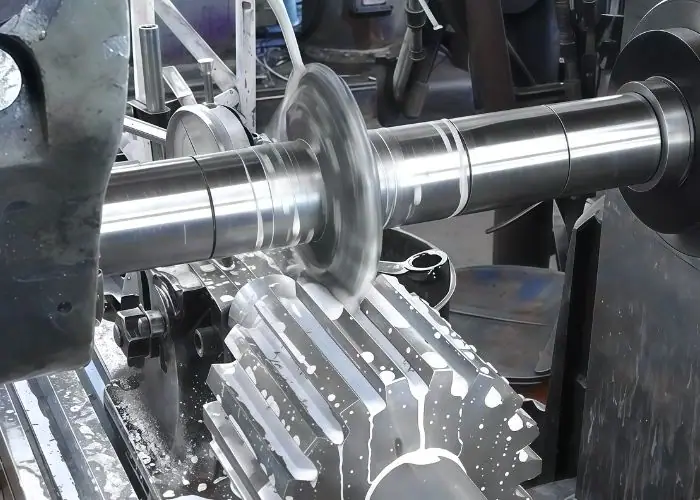
Troubleshooting plain milling should begin with the machining system. If a surface is rough, the cause may be tool wear, chatter, chip recutting, or incorrect feed rate. If thickness is inconsistent, the cause may be clamping distortion, cutter deflection, or machine setup error.
Solving the problem requires identifying the root cause. Changing the drawing tolerance or repeating the same cut will not fix a weak setup, dull cutter, or unstable arbor.
| मुसीबत | संभावित कारण | व्यावहारिक समाधान |
| चैटर चिह्न | Weak setup, excessive cutting load | Improve rigidity and reduce depth of cut |
| ख़राब सतह फ़िनिश | Worn cutter, vibration, poor feed | Use sharper cutter and optimize parameters |
| उपकरण का तेजी से घिसना | High speed, hard material, poor coolant | Adjust speed and use proper tool material |
| चिप पैकिंग | खराब चिप निकासी | Improve coolant, air blast, or cutter geometry |
| गड़गड़ाहट गठन | Dull cutter or ductile material | Use sharp tooling and correct feed |
| Flatness error | Clamping distortion or uneven stock removal | Improve support and use finishing pass |
| मोटाई में भिन्नता | Tool deflection or setup error | Check cutter, arbor, and machine alignment |
बकबक और कंपन
Chatter appears as repeated marks, noise, or unstable cutting. It is often caused by weak clamping, excessive depth of cut, tool runout, insufficient arbor support, or machine rigidity problems. If chatter is ignored, it can damage the surface and shorten tool life.
To reduce chatter, improve the fixture, reduce tool overhang, check arbor support, reduce cutting load, and use a more stable cutter. A rigid setup is usually the most important first step.
ख़राब सतह फ़िनिश
Poor surface finish can result from worn cutter teeth, incorrect feed rate, unstable cutting, chip recutting, or poor cutter geometry. Heavy-duty roughing cutters may also leave a rougher surface, especially when used with aggressive parameters.
To improve finish, use a sharper cutter, reduce vibration, optimize speed and feed, improve coolant flow, and consider a lighter finishing pass. If the final finish requirement is very high, another finishing operation may be needed.
तेज़ उपकरण घिसाव
Fast tool wear may be caused by excessive cutting speed, hard or abrasive material, poor coolant, incorrect tool material, or rubbing. Tool wear affects surface finish, dimensional control, and cutting force.
To reduce tool wear, choose the correct cutter material and coating, match parameters to the material, avoid rubbing, and monitor tool condition during production. Tool-life planning is important for repeat work.
Chip Packing and Poor Chip Evacuation
Chip packing happens when chips remain in the cutting zone instead of clearing away. This can cause surface scratches, heat buildup, cutter damage, burrs, and poor finish. It is more likely when the cutter lacks chip space or the material produces long chips.
Solutions include improving coolant direction, using air blast where suitable, reducing cutting load, changing cutter geometry, or adjusting feed and speed. Chip control is a key part of process stability.
Inaccurate Flatness or Thickness
Flatness and thickness errors can come from poor support, clamping distortion, cutter deflection, thermal growth, uneven stock removal, or internal material stress. Large or thin parts are especially sensitive.
To improve accuracy, support the workpiece properly, avoid over-clamping, use staged machining, remove material evenly, and finish with a stable light pass. Inspection should confirm both thickness and flatness.
Where Is Plain Milling Commonly Used?
Plain milling is commonly used to machine broad flat surfaces, prepare reference faces, reduce stock thickness, and create stable mounting surfaces on machine parts, base plates, structural components, automotive parts, aerospace components, medical equipment parts, and industrial equipment. It is especially useful when large surfaces need efficient and controlled material removal.
Many machined components begin as blocks, plates, castings, or forgings with extra material. Plain milling can remove that material and establish a flat surface before drilling, boring, end milling, grinding, or assembly. This makes it valuable as both a roughing and preparation process.
Plain milling is not limited to one industry. Its value comes from flatness, stable cutting, and productivity. Whenever a part needs a broad surface prepared accurately and efficiently, plain milling may be considered.
| आवेदन क्षेत्र | विशिष्ट भाग | Why Plain Milling Is Useful |
| आधार प्लेटें | Fixture plates, machine bases | Creates flat reference surfaces |
| मशीन के पुर्जे | Blocks, slides, structural parts | Prepares mounting and contact areas |
| मोटर वाहन | Housings, brackets, flat surfaces | उत्पादन में एकरूपता को बढ़ावा देता है |
| एयरोस्पेस | Structural parts and plates | Helps prepare precision surfaces |
| चिकित्सा उपकरण | Platforms, fixtures, housings | Supports stable assembly |
| औद्योगिक उपकरण | Large plates and frames | कुशल सामग्री निष्कासन |
Flat Surfaces and Base Plates
Base plates often require stable flat surfaces so they can support other components accurately. Plain milling can create a reference face before additional machining features are added. This is useful for fixtures, automation equipment, machine bases, and structural assemblies.
If the base surface is uneven, later assembly may suffer from gaps, misalignment, or uneven loading. A controlled plain milling process helps reduce these risks.
Machine Components and Structural Parts
Machine components may require flat faces for mounting, sliding, locating, or clamping. Plain milling can prepare these areas efficiently, especially when the surface is wide and accessible.
Structural parts may also require controlled thickness or flat contact areas. In these cases, plain milling can serve as an early step before other precision machining operations.
वाहन के पुर्जे़
Automotive components may use plain milling for housings, brackets, engine-related surfaces, and structural features. The process can help prepare flat areas for assembly or further machining.
In production environments, repeatability is important. Stable fixtures, controlled parameters, and tool-life management help maintain consistency across batches.
एयरोस्पेस घटक
Aerospace components often require accurate surfaces, stable material removal, and careful distortion control. Plain milling may be used to prepare stock or reference surfaces before more complex machining.
Because aerospace parts can involve high-value materials and strict inspection, process planning is especially important. Workholding, material removal sequence, and inspection should be controlled carefully.
चिकित्सा उपकरण भाग
Medical equipment parts may include housings, plates, fixtures, and precision platforms. Plain milling can help create flat, stable surfaces needed for assembly and alignment.
For medical-related applications, burr control, surface quality, and inspection are important. Even if the geometry is simple, the part may require consistent quality and documented control.
निर्माण और औद्योगिक उपकरण
Construction and industrial equipment often uses large structural components, plates, and frames. Plain milling can prepare flat mounting faces, reduce stock, and create surfaces for later drilling or assembly.
The process is useful when durability and fit matter, even if the part does not require extremely tight cosmetic finishing.
What Safety Considerations Matter In Plain Milling?
Plain milling safety depends on secure workholding, correct cutter and arbor installation, proper machine guarding, safe chip control, coolant management, and operator protection. Because plain milling uses rotating cutters and strong cutting forces, unsafe setup can lead to workpiece movement, flying chips, tool damage, entanglement, burns, or serious injury.
Safety should be considered before machining begins. The operator should confirm that the workpiece is clamped, the cutter is secure, the arbor is supported, guards are in place, speeds are suitable, and emergency controls are accessible. Chip removal should never be done by hand while the machine is running.
A safe process also protects part quality. Loose workholding, damaged cutters, or uncontrolled chips are not only safety risks, they also cause poor surface finish, tool wear, and scrap parts.
| सुरक्षा क्षेत्र | जोखिम | सुरक्षित अभ्यास |
| workholding | वर्कपीस मूवमेंट | Clamp and support securely |
| Cutter mounting | Tool loosening or breakage | Inspect cutter and arbor setup |
| रोटेशन | नाज़ुक हालत | Keep hands, hair, and clothing away |
| चिप्स | Cuts or eye injury | Use guards and eye protection |
| शीतलक | Slippery floors or mist | Manage coolant flow properly |
| गर्मी | Burns from hot chips | Use safe chip handling tools |
Workpiece Clamping Safety
The workpiece must be clamped securely before cutting begins. If it moves during the operation, it can damage the part, cutter, machine, or operator. Support should be placed where cutting forces are expected.
Clamping should also avoid part distortion. Over-clamping a thin or long workpiece may bend it, causing poor flatness after release. Safe clamping must be both strong and controlled.
Cutter and Arbor Safety
The cutter and arbor should be installed correctly and inspected before machining. Damaged teeth, loose spacers, poor arbor support, or incorrect mounting can create vibration or cutter failure.
The operator should also confirm that the cutter direction and machine speed match the operation. An incorrect setup can quickly become both a safety issue and a quality issue.
Chip, Coolant, and Operator Protection
Plain milling can create hot, sharp chips. Operators should use eye protection, machine guards, and proper chip-removal tools. Chips should not be cleared with bare hands or while the cutter is running.
Coolant should be directed properly to support cutting and chip evacuation. Poor coolant control can create slippery floors, mist, poor visibility, or ineffective heat removal.
अक्सर पूछे जाने वाले प्रश्न
What Is The Difference Between Plain Milling And Face Milling?
Plain milling uses the cutter’s peripheral teeth, with the cutter axis generally parallel to the machined surface. Face milling uses the cutter face, with the tool axis usually perpendicular to the surface. Plain milling is often used for broad stock removal on flat surfaces, while face milling is commonly used to improve top surface finish. In many CNC machining processes, plain milling may prepare the surface first, and face milling may be used later for a smoother final result.
What Is Another Name For Plain Milling?
Another common name for plain milling is slab milling. It may also be described as peripheral milling when the focus is on the cutter’s outside-edge cutting action. These terms are closely related because they all involve material removal from a flat surface using the cutter’s circumference. However, drawings and process plans should still define the required surface, tolerance, cutter type, and finish clearly instead of relying only on the name of the operation.
Is Plain Milling Dangerous?
Plain milling can be dangerous if the workpiece, cutter, arbor, chips, or machine guards are not properly controlled. The main risks include entanglement, flying chips, hot swarf, cutter breakage, workpiece movement, and burns. The process can be made safer by using secure workholding, correct cutter installation, suitable speed and feed, machine guarding, eye protection, and safe chip-handling practices. Like other milling operations, plain milling depends on disciplined setup and operation.
Is Slab Milling The Same As Plain Milling?
Slab milling is often considered the same as plain milling because both use a wide cylindrical cutter and peripheral cutting action to machine flat surfaces. The term slab milling often emphasizes broad stock removal with a slab-style cutter, while plain milling describes the operation more generally. In practical machining language, they are frequently interchangeable, but the exact requirement should still be defined by cutter type, machine setup, surface size, tolerance, and the intended machining result.
निष्कर्ष
Plain milling is a practical milling method for machining broad, flat surfaces, reducing stock thickness, and preparing reference faces for later manufacturing steps. Although the process is straightforward, reliable results depend on cutter selection, machine rigidity, arbor setup, workholding stability, cutting parameters, material behavior, coolant control, and inspection.
At टायरैपिड, we provide precision CNC machining and manufacturing services for custom metal and plastic components. Our team supports CNC milling, turning, DFM analysis, material selection, surface finishing, and quality inspection to help customers produce accurate, stable, and manufacturable parts for real engineering applications.
















