Gears transfer motion and power between components in equipment ranging from small actuators to industrial gearboxes. Although a gear may look like a simple toothed wheel, its performance depends on more than the shape of its teeth. The bore, faces, material, hardness, and relationship between features all affect how the part fits and operates.
Gear machining brings these requirements together through operations such as turning, milling, tooth cutting, and finishing. The right process depends on the gear design, required accuracy, material, and production quantity.
This guide explains common gear machining methods, the role of CNC machining, and the quality considerations engineers and buyers should understand when ordering custom gears.
Mitä on hammaspyörän koneistus?
Gear machining is the use of material removal processes to produce the teeth and other functional features of a gear. It can include preparing the gear blank, cutting the teeth, machining mounting features, and finishing critical surfaces.
What Is The Difference Between Gear Machining And Gear Cutting?
Gear cutting refers specifically to producing the tooth geometry. Hobbing, shaping, and form milling are examples of processes used to create gear teeth.
Gear machining covers a broader range of operations. Before teeth are cut, the manufacturer may turn the blank to establish its outside diameter, bore, and faces. After tooth cutting, the gear may require additional operations such as grinding, deburring, or machining a keyway.
The distinction matters when requesting a quote. A supplier that can machine a gear blank may not necessarily perform every tooth cutting or gear inspection operation required for the finished part.
What Is The Role Of CNC In Gear Machining?
CNC stands for computer numerical control. It describes how a machine follows programmed instructions to control movements and machining operations.
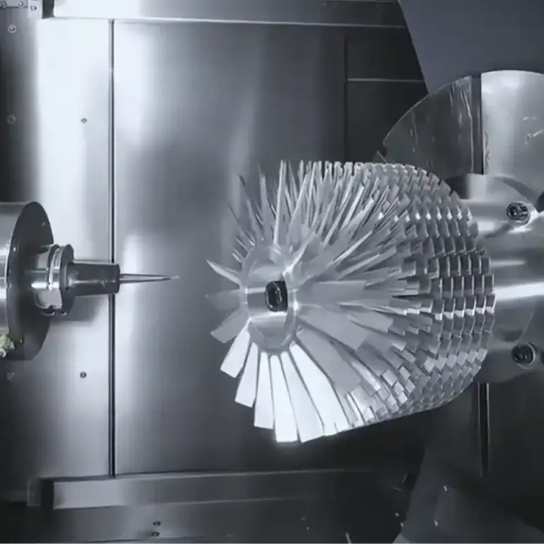
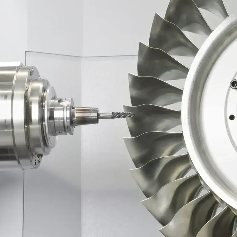
CNC turning is commonly used to produce round features such as gear blank diameters, bores, faces, and shoulders. CNC milling can create mounting holes, slots, and other non-round features. With suitable equipment, tooling, and programming, milling can also produce certain gear tooth forms.
Some dedicated gear machines, including hobbing, shaping, and grinding machines, also use CNC controls. The process used to form the teeth and the control system used to operate the machine should therefore be considered separately.
Why Does Gear Quality Matter?
A gear must mesh with another component while maintaining the required relationship with its shaft, bearing, or housing. If the teeth are incorrectly spaced, or if the bore is poorly located relative to the tooth system, the assembly may experience uneven contact, vibration, or accelerated wear.
Gear quality is therefore a combination of tooth accuracy, material condition, surface quality, and the dimensions needed for assembly. The most useful quality requirements are those linked to how the gear will operate.
What Types Of Gears Can Be Machined?
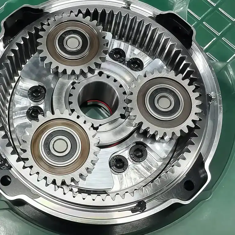
Common machined gears include spur, helical, internal, bevel, and worm gears. Their tooth direction and overall geometry affect tool access, machine selection, and inspection requirements.

Spur And Helical Gears
Spur gears have teeth that run parallel to the gear axis. Their relatively straightforward geometry makes them a common starting point for discussing gear cutting.
Helical gears have teeth that follow an angled path around the gear. Their geometry requires control of both the tooth profile and its alignment across the gear face. They can be used where the design calls for smoother engagement, although their angled teeth also produce axial forces that the assembly must accommodate.
Both types are available in many sizes and materials. The appropriate machining method depends on the complete design, not only on whether the teeth are straight or angled.
Internal And Bevel Gears
Internal gears have teeth on the inside of a ring or other enclosed feature. The surrounding material limits tool access, so processes such as gear shaping or power skiving may be considered when suitable for the part.
Bevel gears typically transmit motion between intersecting shafts. Their tapered geometry requires a process suited to the specific tooth design. Some bevel gear sets are manufactured and checked as matched pairs when their contact pattern is important to the assembly.
Worm Gears And Other Special Geometries
A worm gear assembly combines a worm with a mating worm wheel. Because the components have different shapes and contact conditions, they may require different manufacturing approaches.
Other custom gears may include integrated shafts, narrow shoulders, unusual tooth forms, or limited access around the teeth. These features should be reviewed early because they can influence tooling, workholding, and the available machining methods.
What Are The Main Gear Machining Processes?
Gear hobbing, shaping, power skiving, and milling create tooth geometry, while processes such as grinding, honing, and lapping may be used for finishing. The best choice depends on gear geometry, required quality, tooling, and production volume.
Vaihde Hobbing
Gear hobbing uses a rotating cutting tool called a hob. The hob and gear blank rotate in a coordinated relationship, progressively generating the teeth as the tool moves across the workpiece.
Hobbing is widely used for external spur and helical gears. Its continuous cutting action can make it an efficient choice when a suitable hob is available and the production quantity supports the setup.
Tool access is an important limitation. A nearby shoulder or another feature may interfere with the hob. Conventional hobbing is generally unsuitable for producing internal gear teeth because the tool cannot reach the tooth spaces in the same way.
Gear Shaping And Power Skiving
Gear shaping commonly uses a reciprocating cutter that moves in a controlled relationship with the gear blank. It can produce external or internal teeth, depending on the cutter and part geometry.
Shaping may be useful when a shoulder or other feature restricts access for a hob. However, cutter clearance and the space needed for the cutting stroke must still be considered.
Power skiving is a continuous cutting process that uses coordinated rotation between the cutter and workpiece. It can be applied to suitable internal and external gears on machines capable of maintaining the required synchronization.
The choice between shaping and skiving depends on the available equipment, gear dimensions, tooling, and production requirements.
CNC Gear Milling
Gear milling removes material from tooth spaces using a suitable cutting tool. A form cutter may be used to produce the required space profile, while other milling strategies can be developed for suitable part geometries.
CNC milling can be useful for prototypes, custom designs, and some low-volume projects where flexible programming and tooling are valuable. It can also be combined with machining of the bore, faces, and other features when the machine and setup allow.
However, milling is not automatically the most suitable method for every gear. Tooth form, access, cutter design, required accuracy, and production quantity must be reviewed before selecting it.
Gear Grinding, Honing, And Lapping
Gear grinding uses an abrasive wheel to finish tooth surfaces. It is often considered for hardened gears when the required tooth geometry or surface condition cannot be achieved by the preceding cutting operation alone.
Honing uses an abrasive tool in controlled contact with the gear to refine the tooth surface. Lapping uses an abrasive compound between mating members to improve their contact condition. Lapping is commonly associated with certain matched gear pairs.
These processes have different purposes and are not interchangeable. Some gears meet their requirements after cutting and do not need additional tooth finishing.
Comparing Gear Machining Methods
| Käsitellä asiaa | Tyypillinen käyttö | Tärkein huomioitava asia |
| Vaihteiston hobbing | External spur and helical gears | Requires suitable hob access and tooling |
| Vaihteen muotoilu | Internal or external gears | Cutter clearance and stroke must suit the part |
| Power skiving | Suitable internal or external gears | Requires synchronized machine motion and suitable tooling |
| CNC gear milling | Custom gears, prototypes, and suitable low-volume parts | Toolpath, cutter, and tooth accuracy must be evaluated |
| Hammaspyörän hionta | Finishing gears requiring controlled tooth geometry | Often considered after hardening when requirements justify it |
| Honing or lapping | Refining tooth surfaces or mating contact | Selection depends on the finishing objective and gear design |
How Is A Gear Made From Blank To Finished Part?
A typical gear manufacturing route begins with a prepared blank, continues through tooth cutting and any required heat treatment, and ends with finishing and inspection. The exact sequence varies with the material, gear design, and acceptance requirements.

CNC Turning And Milling For Gear Blanks
The gear blank is the starting shape from which the teeth will be produced. Depending on the design, it may begin as bar stock, a forging, a casting, or another prepared form.
CNC turning can establish the outside diameter, bore, faces, and shoulders. These features provide the surfaces needed to locate the part during later operations and to fit it into the final assembly.
CNC milling may add mounting holes, slots, flats, or other features. The machining plan should consider which surfaces will serve as datums so that the teeth can be positioned correctly relative to the bore or shaft.
Tooth Cutting And Supporting Features
After the blank is prepared, the manufacturer cuts the teeth using a process suited to the gear. The setup must locate the part consistently and provide access across the required tooth width.
Other features may include keyways, splines, threaded holes, oil passages, or retaining grooves. Their machining sequence depends on the gear design and the way the part will be held.
For example, a keyway that affects workholding may be machined at a different stage from one that can be added after tooth cutting. The goal is to protect critical surfaces while maintaining the relationships specified on the drawing.
Heat Treatment And Final Finishing
Some gears require heat treatment to achieve specified material properties. Heat treatment may change dimensions or distort the part, so the process plan may leave material for selected finishing operations.
Depending on the design, a manufacturer may finish the bore, faces, or teeth after heat treatment. The part is then deburred, cleaned, and inspected against the agreed requirements.
Not every gear follows every stage. A gear made from an engineering plastic, for example, will have a different route from a hardened alloy steel gear.
What Materials And Heat Treatments Are Used For Gears?
Gear materials are selected according to load, wear, corrosion, weight, and operating conditions. Heat treatment may also be specified to develop the hardness and material properties needed for the application.
Hiiliteräs ja seosteräs
Carbon and alloy steels are common choices for gears that must carry mechanical loads. The appropriate grade depends on the required strength, wear resistance, machinability, and heat treatment response.
Some designs require a hard tooth surface while retaining a tougher core. Others may use a different combination of properties based on the load and expected service conditions.
When ordering, specify the required material grade and condition rather than using a broad description such as “steel.” If hardness or case depth is important, those requirements should also appear on the drawing or supporting specification.
Stainless Steel, Nonferrous Metals, And Engineering Plastics
Stainless steels may be selected when corrosion resistance is important. The specific grade still needs to suit the load, wear, and manufacturing requirements of the gear.
Nonferrous metals, including bronze and aluminum alloys, may be used in suitable applications. Bronze is used in some worm wheel designs, while aluminum may be considered when weight is a significant concern.
Engineering plastics such as acetal and nylon can be used for selected light-duty or specialized applications. Their behavior under load, temperature, moisture, and repeated operation must be considered during material selection.
How Does Heat Treatment Affect A Gear?
Heat treatment can change hardness, strength, wear resistance, and other material properties. Common approaches for suitable steels include through hardening, carburizing, and nitriding.
The process must be matched to the material and the required properties. It can also introduce dimensional change or distortion, which is why the manufacturing plan should account for any necessary post-treatment machining.
A complete specification should identify the required treatment and acceptance criteria. Depending on the application, these may include surface hardness, core properties, or case depth.
What Affects Gear Machining Accuracy?
Gear accuracy is influenced by tooth geometry, machine and tool condition, workholding, material behavior, and heat treatment. The required accuracy should be defined in relation to the gear’s operating and assembly needs.
Tooth Geometry And Accuracy Requirements
A gear drawing may define parameters such as tooth count, module or diametral pitch, pressure angle, and helix angle where applicable. It may also specify tooth quality requirements using an applicable standard and grade.
These details help the manufacturer select tooling and determine how the gear should be measured. A model that shows the approximate shape may not communicate all the information required to manufacture and inspect the teeth.
Gear accuracy and general dimensional tolerances are related, but they do not describe the same characteristics. A close bore tolerance alone does not establish acceptable tooth profile or pitch.
Datums, Workholding, And Machine Setup
The gear must be located consistently during machining. If the bore or shaft is used as the mounting reference in the finished assembly, its relationship to the tooth system is particularly important.
Workholding errors can affect how the teeth are positioned relative to that reference. Excessive clamping force may also deform a thin part, while insufficient support can allow movement during cutting.
A well-planned setup considers both the feature being machined and the surfaces that will be used to locate the gear during inspection and assembly.
Tool Wear And Heat Treatment Distortion
A worn or unsuitable cutting tool can affect tooth form and surface condition. Machine setup, cutting conditions, and tool maintenance all contribute to the consistency of the result.
Heat treatment adds another source of variation for gears that require hardening. The amount and direction of dimensional change depend on the part, material, and process.
Manufacturers can account for these factors through process planning, suitable allowances, and checks at appropriate stages. The final route should be based on the drawing requirements rather than an assumed tolerance for every gear.
How Is Gear Quality Inspected?
Gear inspection checks the tooth characteristics, mounting features, material condition, and surface quality specified for the part. The measurement method and acceptance criteria should be agreed before production.

Tooth Profile, Lead, Pitch, And Runout
Tooth profile describes the shape of the tooth flank in the profile direction. Lead describes the tooth alignment across the gear face. Pitch relates to the spacing of the teeth around the gear.
Runout checks are used to evaluate variation related to the position of the tooth system as the gear rotates about a reference axis. The exact characteristic and measurement method should follow the drawing or applicable standard.
Together, these checks can help identify whether the tooth system meets the requirements for the intended assembly.
Bore, Dimensions, And Geometric Tolerances
A gear also has ordinary dimensional and geometric requirements. These may include bore diameter, outside diameter, face width, keyway dimensions, and the relationship between mounting surfaces.
A gear can have acceptable tooth geometry but still fail to fit its shaft if the bore is incorrect. Likewise, an incorrectly located face or shaft feature can affect assembly even when individual dimensions appear acceptable.
Inspection should therefore cover both the teeth and the features that locate the gear in use.
Hardness, Surface Condition, And Functional Checks
Where heat treatment is specified, hardness checks help verify the required material condition. Additional metallurgical checks may be needed when the drawing specifies requirements such as case depth.
Visual and surface checks can identify burrs, damage, or other defects that may affect assembly or operation. A functional check, such as a contact or meshing test, may also be appropriate for certain gear pairs.
Functional testing and dimensional measurement provide different information. One should not be assumed to replace the other unless the acceptance plan specifically allows it.
Gear Inspection Methods And Equipment
A gear measuring machine can assess specified tooth characteristics such as profile, lead, and pitch. The exact measurements available depend on the equipment and inspection setup.
A coordinate measuring machine, or CMM, can inspect many dimensions and geometric relationships on the blank and mounting features. Some CMM systems can also inspect gear features when equipped and configured for the task.
Hardness testers, surface measuring instruments, gauges, and functional test equipment may be used according to the requirements. Buyers should confirm the inspection method and report format before placing an order.
How Do You Choose A Gear Machining Process And Supplier?
Choose a process and supplier by reviewing the gear geometry, material, required accuracy, quantity, and inspection needs together. A clear drawing and complete inquiry help the supplier assess a suitable manufacturing route.
Match The Process To Gear Geometry And Quantity
Start with the gear type and the features surrounding the teeth. An accessible external gear may be suitable for hobbing, while an internal gear may require consideration of shaping or power skiving.
Next, review quantity and tooling. A process that is practical for repeated production may not be the best choice for a prototype if dedicated tooling or setup requirements are significant.
The final decision should also consider material, required tooth quality, available equipment, and any finishing operations.
Balance Accuracy, Lead Time, And Cost
Tighter requirements can affect machining, inspection, and the number of operations needed. Heat treatment and specialized finishing may also influence the production schedule.
The aim is to specify the accuracy needed for the gear to perform its function. For example, a critical bore-to-tooth relationship should be clearly controlled when it affects assembly. Features with less influence on operation can be toleranced according to their actual purpose.
Discussing these requirements early gives the manufacturer an opportunity to identify potential issues before production begins.
What Should You Include In A Custom Gear Inquiry?
A useful inquiry gives the supplier enough information to understand both the gear teeth and the rest of the part. Include the following where applicable:
- A dimensioned drawing and a 3D model.
- Gear type, tooth count, module or diametral pitch, and pressure angle.
- Helix angle and direction for a helical gear.
- Material grade, heat treatment, hardness, and any required case depth.
- Gear accuracy requirements and applicable standards.
- Bore, shaft, keyway, mounting, and geometric tolerance requirements.
- Surface finish, inspection reports, quantity, and required delivery date.
- Mating gear or assembly information when it is relevant to fit or contact.
If the drawing is incomplete, share the available information and identify which requirements still need to be confirmed. A sample may help explain the part, but it does not automatically define every design or acceptance requirement.
Confirm CNC Machining And Gear Inspection Capabilities
Ask the supplier which operations can be completed for the specific part. These may include CNC turning of the blank, milling of mounting features, tooth cutting, heat treatment, finishing, and inspection.
For a gear with demanding tooth requirements, confirm how the relevant tooth characteristics will be measured and documented. It is also useful to clarify which operations will be performed in-house and which may require an external specialist.
This discussion helps align the drawing, manufacturing route, and inspection plan before a quotation or production schedule is finalized.
UKK
How Are Gears Machined?
Gears are typically machined by preparing a blank, cutting the teeth, and machining features such as bores and keyways. Heat treatment and finishing may follow, depending on the design.
How Are Gears Cut On A Milling Machine?
A milling machine cuts the tooth spaces using a suitable cutter. The gear blank is indexed between cuts to produce the required number and spacing of teeth.
What Is A Gear Hobbing Machine?
A gear hobbing machine cuts teeth using a rotating tool called a hob. The hob and gear blank rotate in a coordinated motion to generate the tooth profile.
Yhteenveto
Gear machining combines tooth cutting with the production of bores, faces, shafts, and other features needed for assembly. The right manufacturing route depends on the gear geometry, material, accuracy requirements, and quantity. Inspection should verify both the tooth system and the features that locate the gear in use.
TiRapid provides CNC milling and turning services for custom parts. If your project includes a gear blank or related machined components, send your drawings, material, tolerances, and quantity for review. The required tooth cutting, heat treatment, and inspection can be evaluated according to the specific project.