As AI computing, high-performance servers, and data centers continue to generate more heat, traditional air cooling is becoming less effective for high-density equipment. Liquid cooling provides a more direct way to transfer heat, but its performance depends on more than pumps and cold plates. The liquid cooling manifold also plays an important role in distributing coolant throughout the system.
A manifold must deliver the required coolant flow to every connected server while maintaining reliable connections, controlled pressure, and leak-free operation. Its internal channels, branch positions, material selection, and machining accuracy all affect system performance.
What Is A Liquid Cooling Manifold?
A liquid cooling manifold is a fluid distribution component that divides coolant from a central supply into multiple branches and collects the warmed coolant for return. It connects the coolant distribution unit (CDU) to individual servers or cold plates, helping maintain stable coolant delivery throughout the system.
Main Functions Of A Liquid Cooling Manifold
A liquid cooling manifold mainly distributes coolant, collects return fluid, and provides organized connection points for multiple cooling branches. These functions help maintain consistent thermal conditions across a liquid-cooled server rack.
When several servers operate simultaneously, each server may require a different coolant flow rate depending on its heat load and cold plate design. The manifold must therefore support the required flow distribution without creating excessive pressure loss.
Selle peamised funktsioonid hõlmavad järgmist:
- Coolant Distribution: Divides the main supply flow into multiple branches serving individual servers or cold plates.
- Return Collection: Combines warmed coolant from different branches and sends it back to the CDU.
- Flow Management: Supports balanced branch flow through suitable internal passages and optional balancing valves.
- System Connection: Provides interfaces for hoses, quick disconnects, isolation valves, and monitoring components.
- Maintenance Support: Allows individual branches to be isolated or disconnected without unnecessarily disturbing the entire cooling loop.
Key Components And Basic Structure
A typical liquid cooling manifold consists of supply and return headers, branch outlets, connection ports, valves, and mounting structures. These components work together to distribute coolant and maintain secure connections between the cooling system and server equipment.
| Komponent | Peamine funktsioon |
| Supply Header | Receives coolant from the CDU and distributes it to branches |
| Return Header | Collects warmed coolant and returns it to the CDU |
| Haru sadamad | Connect individual servers or cold plate circuits |
| Isolatsiooniklapid | Shut off selected branches during maintenance |
| Kiired ühendused | Allow fast hose connection and disconnection with minimal fluid loss |
| Drain And Vent Ports | Support coolant draining and trapped-air removal |
| Kinnitusklambrid | Secure the manifold inside or around the rack |
The internal passage layout is particularly important because it determines how coolant reaches each branch. Poorly positioned outlets or undersized passages can create uneven flow, making some servers receive less cooling than others.
How Does A Liquid Cooling Manifold Work?
A liquid cooling manifold works by receiving conditioned coolant from the CDU, dividing it into individual supply branches, and collecting the warmed coolant through a separate return path. This creates an organized circulation route between the cooling equipment and connected servers.
Coolant Supply From The CDU To The Rack
The CDU supplies conditioned coolant to the manifold through the main inlet connection. The coolant then enters the supply header, which distributes the fluid to multiple branch outlets connected to individual servers.
For a liquid cooled server rack, the manifold is commonly installed at the rear of the rack, where technicians can access the branch connections and hose assemblies. Each outlet must align with the corresponding server position to avoid unnecessary hose bending or interference.
The main supply passage must also be sized according to the total system flow. If its internal diameter is too small, the resulting pressure drop may reduce the flow available to downstream branches.
Coolant Distribution And Return Flow
After entering each branch, coolant travels through connecting hoses and reaches the cold plates installed on heat-generating components. The coolant absorbs heat from CPUs, GPUs, and other electronic devices before returning to the manifold.
The return header collects the warmed coolant from individual branches and directs it back to the CDU. The CDU then transfers heat to the facility cooling circuit through its heat exchanger and circulates conditioned coolant back into the secondary loop.
A typical circulation sequence is:
- The CDU supplies conditioned coolant.
- The supply header distributes coolant to individual branches.
- Branch hoses carry coolant to server cold plates.
- Cold plates absorb heat from electronic components.
- The return header collects warmed coolant.
- The CDU receives the return flow and removes the transferred heat.
How To Maintain Balanced Flow Across Every Branch
Balanced flow is achieved by designing suitable internal passage dimensions, branch resistance, and connection layouts according to the cooling requirements of each server. It does not simply mean making every branch identical.
For example, a high-power GPU server may require more coolant than a lower-power network device. The manifold must account for these differences when determining branch sizes and flow restrictions.
Engineers commonly consider:
- Main header diameter and total flow demand.
- Branch diameter and individual flow requirements.
- Pressure drop across each branch.
- Position and spacing of branch outlets.
- Balancing valves and flow measurement points.
Some commercial manifold designs use adjustable branch valves and test ports to verify flow distribution. One published product specification, for example, describes a manifold with 4–12 branches and branch-level balancing provisions. These values are product-specific rather than universal design requirements.
Main Types Of Liquid Cooling Manifolds
Liquid cooling manifolds are commonly divided into in-rack manifolds and row-based manifolds according to their installation locations and coolant distribution responsibilities. The correct configuration depends on rack layout, system capacity, available space, and maintenance requirements.

Both designs distribute coolant, but they serve different levels of a data center cooling network. Some large installations combine them to support centralized distribution and individual rack connections.
In-Rack Liquid Cooling Manifolds
An in-rack manifold is installed inside or directly behind a server rack to distribute coolant to the servers within that rack. It usually contains separate supply and return headers with multiple branch connections.
This design provides a relatively direct connection between the CDU and individual servers. It also makes maintenance easier because technicians can access the manifold and isolate selected branches without affecting every rack in the facility.
In-rack manifolds are suitable for high-density computing environments where each rack has specific coolant requirements. However, their dimensions, branch spacing, and connection positions must match the rack structure and server configuration.
Row-Based Liquid Cooling Manifolds
A row-based manifold distributes coolant across multiple server racks rather than serving only one rack. It is commonly installed beneath raised floors, above equipment, or along designated distribution routes.
This arrangement allows a central cooling source to supply several racks through a larger distribution network. It is useful for large data centers that require scalable infrastructure and centralized coolant management.
However, longer distribution paths introduce additional pressure-drop and flow-balancing considerations. Engineers must evaluate the total flow demand, pipe dimensions, branch positions, and isolation requirements across the entire row.
Some facilities combine row-based and in-rack designs. The row manifold handles larger-scale distribution, while the in-rack manifold manages the final connections to individual servers.
Key Components And Valve Configurations
Valve configurations determine how coolant branches are isolated, connected, drained, and maintained. A properly designed manifold uses suitable valves, quick disconnects, and service ports to support reliable operation without unnecessarily interrupting the entire cooling system.
Branch Isolation Valves And Ball Valve Selection
Branch isolation valves allow technicians to shut off coolant flow to a selected branch during maintenance or component replacement. Stainless steel ball valves are commonly used because their quarter-turn operation provides straightforward opening and closing.
However, valve selection should consider more than nominal pipe size. The internal bore, pressure drop, sealing material, coolant compatibility, and expected operating cycles all affect long-term performance.
For main flow paths, full-port ball valves are often preferred because their internal opening is close to the connecting pipe diameter. Reduced-port designs introduce additional flow restriction and may be more suitable for smaller drain or instrument connections.
Server Connection Interfaces And Dripless Service
Server connections typically use dry-break quick disconnects rather than ordinary ball valves. These connectors contain internal shut-off mechanisms that close when the two halves are separated, helping reduce coolant loss during maintenance.
This design allows technicians to remove or replace a server without draining the entire liquid cooling loop. It is particularly useful in data centers where equipment maintenance must be completed without unnecessary downtime.
The connection interface must match the hose diameter, flow requirement, pressure rating, and mechanical installation space. Blind-mate connectors also require accurate alignment between the manifold and server tray.
Filtration And Check Valves
Filters and check valves help protect the cooling loop from contamination and unwanted reverse flow. They are not simply optional accessories when the system requires controlled fluid cleanliness and pump protection.
Filters capture particles that could otherwise enter cold plate microchannels. Check valves prevent coolant from flowing backward when a pump stops or when redundant pumps operate under different conditions.
Tüüpiline süsteem võib sisaldada järgmist:
| Komponent | Eesmärk | Disaini kaalumine |
| Y-kurn | Captures solid particles | Mesh size and service access |
| Kontrollventiil | Prevents reverse flow | Opening pressure and installation direction |
| Drain Valve | Allows coolant removal | Port size and accessibility |
| Õhu ventilatsioon | Releases trapped air | Location at high points |
| Pressure Test Port | Supports system verification | Thread type and measurement range |
The filtration requirements should be determined by the cooling system specification. Fine particles can obstruct small cold plate passages, so internal cleanliness must be considered throughout manufacturing and installation.
End Connections, Valve Seats, And Stems
Manifold connections may use threaded ports, welded joints, hose connections, or quick disconnects depending on their position in the cooling loop. Each connection method has different requirements for installation, sealing, and maintenance.
Threaded connections are convenient for serviceable components, while welded connections can reduce the number of detachable joints in permanent piping. Quick disconnects are especially useful at server interfaces where frequent equipment replacement is expected.
Valve seats and stem seals also deserve attention because they directly affect leakage performance. Materials such as PTFE and compatible elastomers may be selected according to coolant chemistry, temperature, and operating cycles.
Key Design And Material Considerations
Liquid cooling manifold design must account for coolant flow, pressure drop, material compatibility, operating conditions, and internal cleanliness. These factors determine whether coolant can reach every branch reliably without causing corrosion, excessive resistance, or leakage.
A manifold should be designed around the actual rack configuration rather than selected only by its external dimensions. The internal passages and wetted materials are just as important as the mounting structure.
Material Selection: 304 Vs. 316 Stainless Steel
304 and 316 stainless steel are common material options for liquid cooling components. Both provide good corrosion resistance, but their chemical compositions and resistance to specific coolant conditions are different.
316 stainless steel contains molybdenum, which improves its resistance to chloride-related pitting corrosion. It may therefore be preferred when the coolant chemistry or operating environment presents a higher corrosion risk.
304 stainless steel can also be suitable for certain controlled closed-loop systems. The final selection should consider coolant additives, chloride concentration, operating temperature, and the material requirements of connected components.
| MATERJAL | Peamised omadused | Design kaalutlused |
| 304 roostevabast terasest | Good general corrosion resistance and manufacturability | Suitable for many controlled coolant environments |
| 316 roostevabast terasest | Improved resistance to chloride pitting | Often preferred for more demanding corrosion conditions |
| messing | Good machinability and established use in fluid connections | Requires coolant and galvanic compatibility checks |
| Alumiinium | Kerge ja hõlpsasti töödeldav | Requires careful coolant compatibility and galvanic corrosion assessment |
Full-Port Vs. Reduced-Port Designs
Full-port and reduced-port designs describe the internal opening of a valve or connection relative to the connected pipe diameter. This difference affects flow resistance and the pressure required to circulate coolant.
A full-port design maintains a larger internal passage and generally creates less additional restriction. A reduced-port design uses a smaller opening, which can reduce component size and cost but introduces additional pressure loss.
For this reason, engineers often prefer full-port valves in main coolant flow paths. Reduced-port connections may be acceptable for smaller drain ports or instrumentation points where the flow requirement is limited.
Flow Balance, Pressure Drop, And Coolant Compatibility
Flow balance and pressure drop must be evaluated together because changing one branch’s resistance can affect the distribution across other branches. A manifold with poorly sized internal channels may cause some servers to receive insufficient coolant.
Coolant compatibility is equally important. Common fluid choices include treated water and inhibited propylene glycol mixtures, while other cooling architectures may use different fluid types.
Projekteerimisel tuleks kinnitada:
- Total system flow and individual branch flow.
- Main header and branch passage dimensions.
- Pressure drop through valves and fittings.
- Coolant composition and additive package.
- Compatibility between metals, seals, hoses, and connectors.
Operating Pressure, Temperature, And Cycle Life
The manifold must withstand the maximum expected operating pressure and temperature without permanent deformation or loss of sealing performance. These limits should come from the system design rather than from a generic manifold specification.
For reference, one commercial 316L manifold lists a 1.0 MPa design pressure and a 1.5 MPa pressure test lasting 30 minutes. Its stated coolant temperature range is -20°C to +65°C. These are example product specifications, not universal requirements for every application.
Rack Level Coolant Distribution
Valve and connector cycle life also matters. Components that are frequently disconnected during server maintenance must maintain sealing performance after repeated connection and disconnection cycles.
Internal Cleanliness And Corrosion Resistance
Internal cleanliness is essential because manufacturing debris, weld scale, and corrosion particles can travel through the cooling loop and obstruct narrow cold plate channels.
The manufacturing process should therefore include suitable deburring, cleaning, flushing, and surface treatment procedures. Welded assemblies may also require controlled welding conditions and post-weld cleaning.
For example, a commercial 316L manifold specifies pickling and passivation with an internal surface roughness of Ra ≤ 0.8 μm. This illustrates how internal surface requirements can be included in a product specification, although the appropriate limit depends on the application.
Liquid Cooling Manifold Vs. CDU: What’s The Difference?
A liquid cooling manifold distributes coolant to individual servers, while a coolant distribution unit (CDU) circulates coolant and transfers heat between the facility cooling system and the IT cooling loop. They work together, but they perform different functions.

The distinction is important when designing a complete liquid cooling system. A manifold cannot replace the CDU because it does not contain the pumping and heat-exchange functions required to manage the overall cooling circuit.
Different Roles In The Cooling Loop
The CDU manages coolant circulation and heat exchange, while the manifold manages coolant distribution and return collection.
| tunnusjoon | Vedeliku jahutuskollektor | CDU |
| Peamine funktsioon | Distributes and collects coolant | Circulates and conditions coolant |
| Pumpama | Tavaliselt ei | Jah |
| Soojusvaheti | Ei | Jah |
| Haruühendused | Multiple server outlets | Main loop connections |
| Peamine disainifookus | Flow paths, ports, and branch balance | Pump capacity, heat transfer, and system control |
How Manifolds And CDUs Work Together
In a typical direct-to-chip system, the CDU receives heat from the IT cooling loop and transfers it to the facility cooling circuit. It then supplies conditioned coolant to the manifold.
The manifold distributes this coolant to individual server cold plates and collects the warmed return flow. This arrangement allows the CDU to manage the overall cooling process while the manifold handles the final distribution throughout the rack.
A well-designed system therefore requires both components to work within compatible flow, pressure, and temperature specifications.
CNC Machining For Custom Liquid Cooling Manifolds
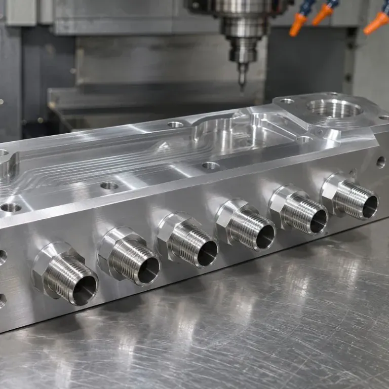
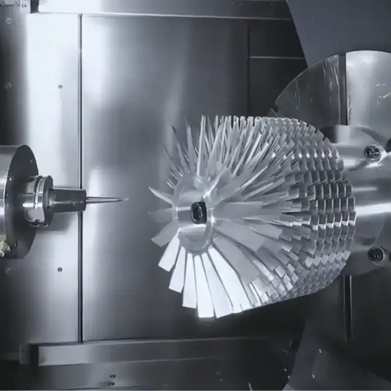
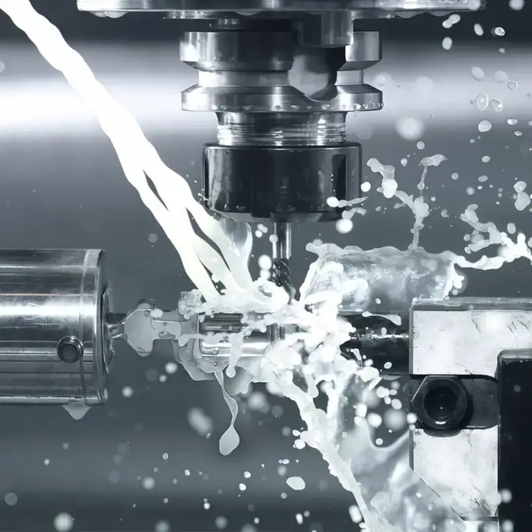
CNC machining produces precision manifold bodies, internal passages, mounting features, ports, and connection interfaces. Milling, drilling, boring, tapping, and 5-axis machining can be combined to create complex coolant distribution structures with controlled dimensions and reliable assembly interfaces.
Not every manifold uses the same manufacturing route. Some designs use machined metal blocks with internal channels, while others use stainless steel tubes with welded branch connections. The manufacturing method should match the required flow path, pressure rating, installation space, and production volume.
CNC Milling Of Manifold Bodies And Internal Channels
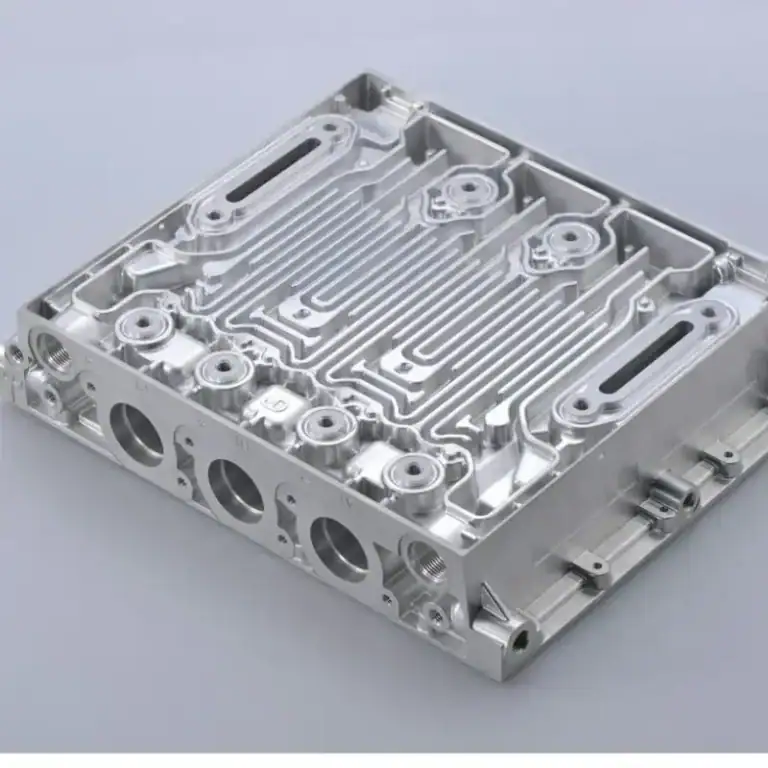
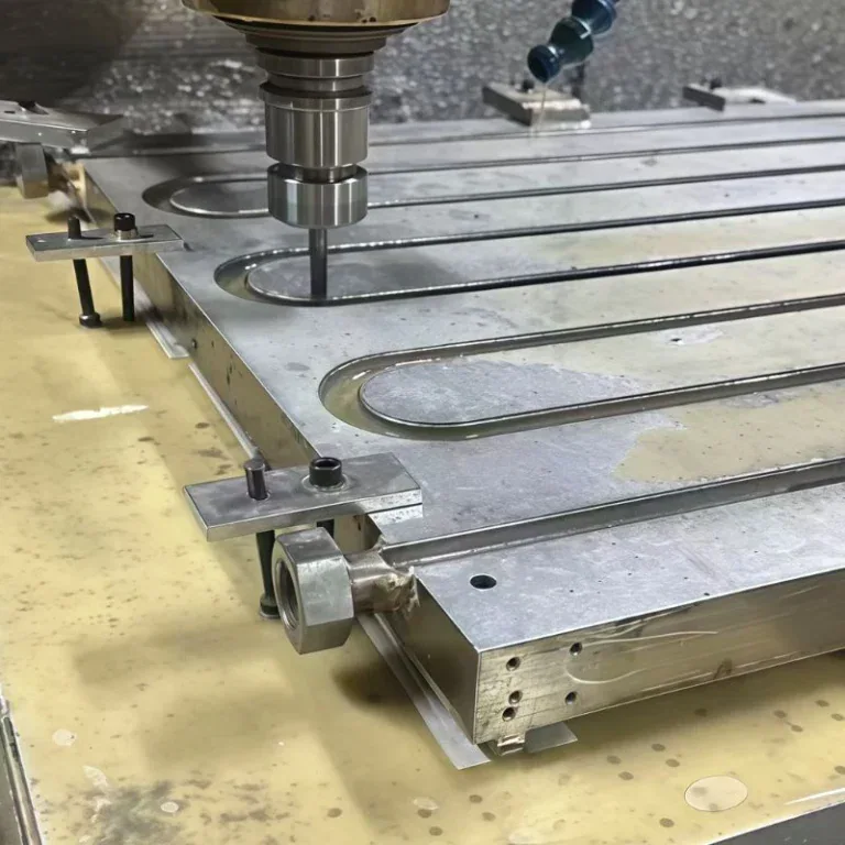
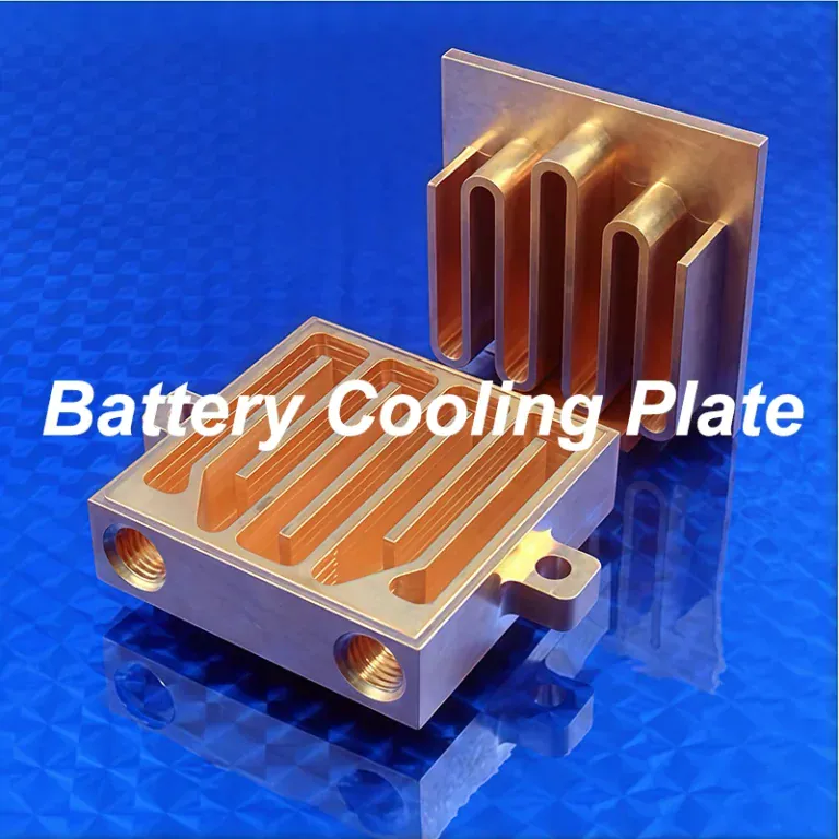
CNC milling is used to machine manifold bodies, mounting surfaces, pockets, and accessible internal flow channels. For block-type manifolds, channels can be milled into the main body before a cover plate or another sealing structure closes the passages.
The machining sequence must preserve the relationship between the internal passages and external connection features. If the ports are incorrectly positioned, the hoses may not align with the server interfaces during assembly.
For complex internal channels, engineers may use a combination of milling, drilling, and multi-piece construction. The design should also consider tool access, chip removal, burr formation, and how internal passages will be cleaned and inspected.
Precision Machining Of Ports, Threads, And Sealing Surfaces
Ports, threads, and sealing surfaces require accurate machining because they directly affect connection fit and leak prevention. Even a small dimensional error can cause assembly difficulties or compromise the sealing interface.
CNC drilling and tapping are commonly used to produce threaded ports, while boring and precision milling can create controlled connection seats and mating surfaces.
Important machining controls include:
- Port Position: Maintain the specified spacing and alignment between connection points.
- Thread Accuracy: Match the required thread type, pitch, and engagement depth.
- Sealing Surface Quality: Control flatness, surface finish, and machining marks.
- Burr Removal: Prevent loose particles from entering the coolant passages.
- Dimensional Inspection: Verify critical features against the engineering drawing.
The required tolerances should be defined according to the connection type and functional requirements rather than applying unnecessarily tight tolerances to every feature.
5-Axis CNC Machining For Complex Manifold Geometries
5-teljeline CNC töötlemine is useful when a manifold contains angled ports, multiple connection faces, or complex geometries that are difficult to access with conventional three-axis machining.
By adjusting the workpiece or cutting tool orientation, a 5-axis machine can access several surfaces in fewer setups. This can reduce repeated clamping, improve positional relationships between features, and make complex machining sequences more practical.
However, 5-axis machining is not automatically necessary for every manifold. Simple block designs may be produced more economically using three-axis or four-axis machining. The decision depends on geometry, tolerance requirements, production quantity, and total manufacturing cost.
Dimensional Accuracy, Surface Finish, And Internal Cleanliness
Dimensional accuracy, surface finish, and internal cleanliness must all be controlled because a manifold is both a precision mechanical component and a fluid-carrying assembly.
External mounting surfaces and connection interfaces determine whether the manifold fits correctly into the rack. Internal passages affect flow resistance and the possibility of contamination. These requirements should be included in the machining plan from the beginning.
Kontroll võib hõlmata järgmist:
| Kontrollpunkt | Mida see kinnitab |
| Mõõtmete ülevaatus | Port positions, hole diameters, and overall geometry |
| Keerme ülevaatus | Thread dimensions and connection compatibility |
| Pinna ülevaatus | Sealing surfaces and specified roughness |
| Sisemine puhastus | Removal of chips, burrs, and machining residue |
| Passage Inspection | Internal geometry and passage continuity |
Inspection, Pressure Testing, And Leak Testing
After machining and assembly, the manifold should undergo inspection and testing according to its approved validation plan. Dimensional inspection confirms that the manufactured features match the drawing, while pressure and leak tests verify the integrity of the fluid passages and connections.
For welded or multi-piece manifolds, testing should also consider joints, cover interfaces, and other potential leakage points. Flow testing can be used to verify that each branch meets its specified flow requirement.
A complete quality process may include:
- Dimensional and thread inspection.
- Visual inspection and deburring verification.
- Internal cleaning and flushing.
- Pressure testing.
- Lekke testimine.
- Branch flow verification, when required.
- Final documentation and traceability.
CNC machining, welding, and final testing should be treated as connected manufacturing stages. Precision machining alone cannot guarantee a leak-free manifold if the assembly and validation processes are not properly controlled.
Reliability And Common Liquid Cooling Manifold Problems
Liquid cooling manifold reliability depends on stable flow distribution, compatible materials, secure connections, and clean internal passages. Problems such as leakage, trapped air, contamination, and uneven branch flow can reduce cooling performance or interrupt server operation.

Because the manifold connects multiple cooling branches, a local problem can affect more than one component. Regular inspection and appropriate design provisions help reduce maintenance risks.
Common Valve And Connection Failures
Valve and connection failures often occur when sealing surfaces wear, threaded joints loosen, or quick disconnects become damaged through repeated operation.
These problems may cause coolant leakage, pressure loss, or difficulty isolating a specific server branch. Connection components should therefore be selected according to their operating pressure, temperature, coolant compatibility, and expected service cycles.
Coolant Contamination, Leakage, And Flow Imbalance
Contamination can obstruct narrow passages inside cold plates, while trapped air may interfere with circulation and cause localized cooling problems. Uneven branch resistance can also result in different flow rates across the rack.
The following issues deserve particular attention:
- Particle Contamination: Machining chips, weld scale, or debris can obstruct small passages.
- Air Entrapment: Air trapped in headers may cause unstable flow and reduce cooling effectiveness.
- Coolant Leakage: Damaged seals or incorrectly assembled connections can lead to fluid loss.
- Flow Imbalance: Poor passage sizing or branch configuration may create uneven cooling.
High-point venting, appropriate filtration, controlled flushing, and pressure testing should be considered during system design and commissioning.
Maintenance And Long-Term System Reliability
Regular maintenance helps identify leakage, contamination, corrosion, and connection wear before they affect the entire cooling system.
Inspection frequency should follow the equipment manufacturer’s recommendations and the operating conditions of the cooling loop. Maintenance planning should include valve operation, quick-disconnect condition, coolant quality, filter condition, and pressure stability.
For systems that require frequent server replacement, accessible branch isolation and dripless connections can significantly simplify service operations.
How To Specify A Custom Liquid Cooling Manifold?
A custom liquid cooling manifold should be specified according to the rack layout, total coolant flow, branch requirements, operating pressure, coolant chemistry, and connection configuration. Providing these details before manufacturing helps engineers select the correct structure and machining method.
A manifold should not be designed using branch count or external dimensions alone. Its internal passages must support the actual cooling requirements of the connected equipment.
Essential Design And Operating Parameters
The first step is to define how the manifold will operate inside the cooling system. Engineers need to understand the total flow demand, the number of connected servers, and the required flow rate for each branch.
Other important information includes the operating pressure, temperature range, coolant type, connection dimensions, and available installation space.
Manufacturing And Supplier Requirements
The manufacturing supplier should be able to review the engineering drawing and evaluate whether the proposed structure can be machined, assembled, cleaned, and tested reliably.
For CNC-machined manifolds, attention should be given to internal passage accessibility, machining tolerances, sealing interfaces, and the possibility of removing chips and burrs.
It is also important to confirm the required inspection records, material certificates, pressure-test procedures, and traceability requirements before production begins.
Liquid Cooling Manifold Specification Checklist
| spetsifikatsioon | Information To Confirm |
| Rack Layout | Rack dimensions, mounting position, and server spacing |
| Branch Configuration | Number of outlets and branch arrangement |
| Voolunõuded | Total flow and individual branch flow rates |
| Internal Passages | Header diameter, channel layout, and flow direction |
| MATERJAL | Stainless steel grade or other approved material |
| Jahutusvedelik | Treated water, glycol mixture, or specified fluid |
| Kasutustingimused | Working pressure and temperature range |
| Side | Thread type, hose fittings, and quick disconnects |
| Valves | Isolation, balancing, drain, and vent requirements |
| Kvaliteedi testimine | Dimensional, pressure, leak, and flow testing |
Providing a complete specification makes it easier to evaluate manufacturing feasibility, avoid unnecessary design changes, and maintain consistent product quality.
KKK
How Many Branches Should A Liquid Cooling Manifold Have?
The number of branches depends on the number of connected servers, cold plate circuits, and required coolant flow. Commercial examples include 4-, 6-, 8-, 10-, and 12-branch configurations, but these are not universal standards. Engineers should calculate the total flow demand, branch resistance, and available installation space before selecting the layout. A manifold with too few outlets may require additional distribution hardware, while excessive branching can increase complexity and pressure losses.
Which Coolant Is Compatible With Stainless Steel Manifolds?
Stainless steel manifolds can work with treated water and compatible inhibited propylene glycol mixtures, provided the coolant chemistry matches the selected material grade and sealing components. Chloride concentration is particularly important because it can increase pitting corrosion risk in stainless steel. Grade 316 offers improved chloride resistance compared with grade 304. Before production, engineers should review the coolant safety data, additive package, operating temperature, and compatibility of all wetted materials.
Why Is Flow Balancing Important In A Liquid Cooling Manifold?
Flow balancing ensures that each server receives the coolant volume required by its thermal load. If one branch has excessive resistance, its connected cold plate may receive insufficient flow, potentially increasing component temperatures. Engineers can evaluate branch pressure drop, passage dimensions, and balancing valve settings during system commissioning. Flow measurements should be compared with the design targets for each branch rather than assuming that identical outlet dimensions will automatically produce equal flow.
Can CNC Machining Produce Internal Cooling Channels?
Yes. CNC machining can produce internal cooling channels through pocket milling, drilling, boring, and cross-hole machining. For channels that cannot be accessed directly, manufacturers may use drilled intersections with sealed access ports, machined covers, or multi-piece constructions. The design must account for tool access, chip removal, sealing integrity, and internal cleaning. Pressure and leak testing should be completed after assembly to verify that the finished passages meet the specified requirements.
Järeldus
A liquid cooling manifold is an important part of modern thermal management systems because it distributes coolant to individual servers and collects warmed fluid for return. Its performance depends on more than branch count or external dimensions. Flow resistance, internal passage geometry, material compatibility, connection reliability, and cleanliness all influence long-term cooling stability.
At TiRapid, we provide precision CNC machining, milling, turning, and multi-axis machining for custom metal components. From manifold bodies and connection ports to complex internal features, our manufacturing team supports drawing review, machining feasibility, and dimensional inspection to help customers produce reliable precision components.