Automatic screw locking machines perform screw feeding, positioning, holding, and tightening operations. The machining quality of their components directly affects equipment stability. Wear on feeding tracks, dimensional deviations in bit holders, or inaccurate positioning fixtures may cause screw jams, missed fastening, or incorrect screw placement. A suitable manufacturing plan should consider component structures, assembly relationships, and operating requirements to select appropriate materials, machining methods, and surface treatments, reducing problems during assembly and commissioning.
Key Components of Automatic Screw Locking Machines and Their Machining Requirements
Different components perform different functions, so their dimensional accuracy and structural requirements should be determined according to their intended applications.
Нийтлэг бүрэлдэхүүн хэсгүүдийн төрлүүд
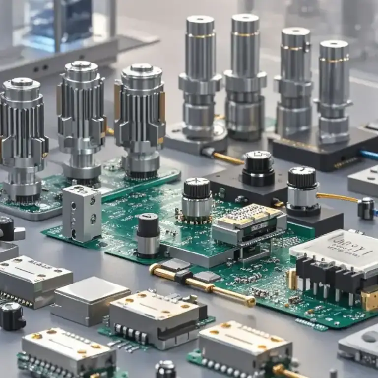
Automatic screw locking machines mainly consist of the following mechanical components:
- Feeding mechanism components: Such as feeding tracks, guide blocks, and screw-separating structures. Their guide slot dimensions and surface conditions must be controlled to ensure smooth screw feeding.
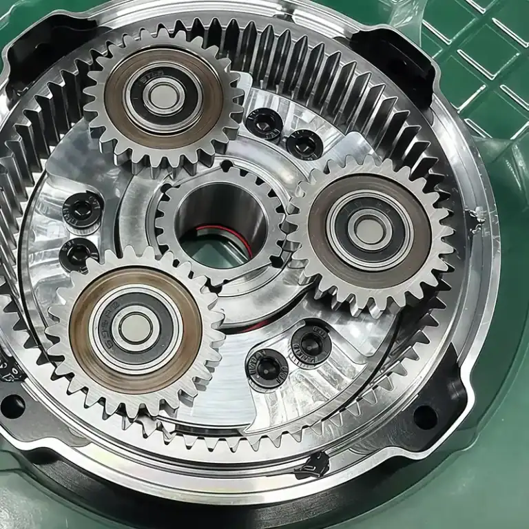
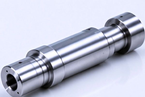
- Fastening mechanism components: Such as bit holders, mounting sleeves, and connecting shafts. Their hole diameters, concentricity, and mating dimensions require accurate machining.
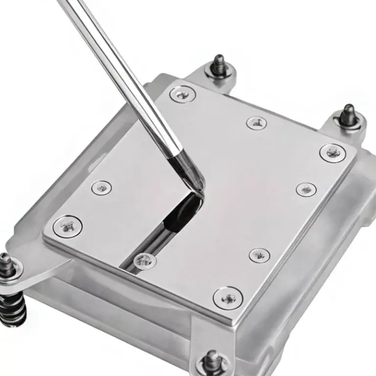
- Positioning fixtures: Used to secure products and determine screw fastening positions. Their locating holes and contact surfaces require sufficient machining accuracy.
- Equipment brackets and bases: Used to mount motors, cylinders, and functional modules. They need sufficient structural rigidity.
Clearly defining each component’s function helps establish suitable material and machining requirements.
Machining Issues That Require Attention
Components have assembly and movement relationships, so local deviations may affect overall equipment performance.
- Feeding position deviations: Inaccurate track widths or guide slot dimensions may cause irregular screw feeding.
- Insufficient clamping accuracy: Deviations in bit mounting holes may affect bit movement and screw alignment.
- Wear on guide surfaces: Continuous friction may cause surface damage or burrs, increasing feeding resistance.
These potential issues should be considered when defining critical dimensions and surface requirements before machining.

How to Select Machining Processes for Automatic Screw Locking Machine Parts?
Machining methods should be selected according to component geometry, material, and accuracy requirements. Different processes can be combined based on structural characteristics.
Select Machining Methods According to Component Geometry
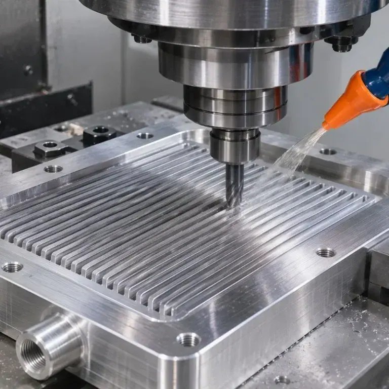
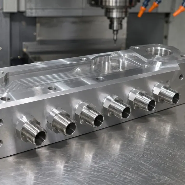
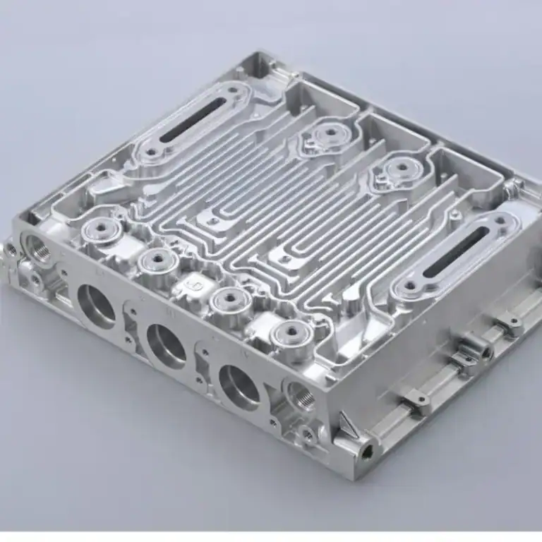
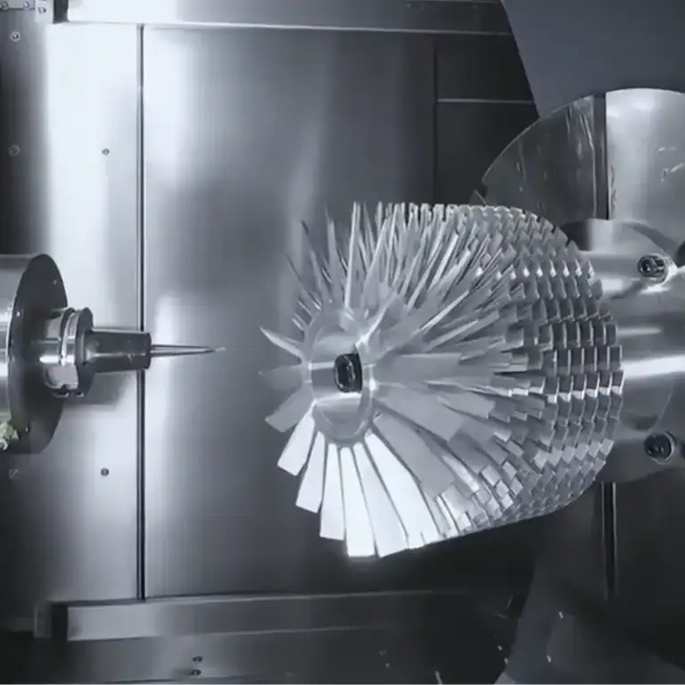
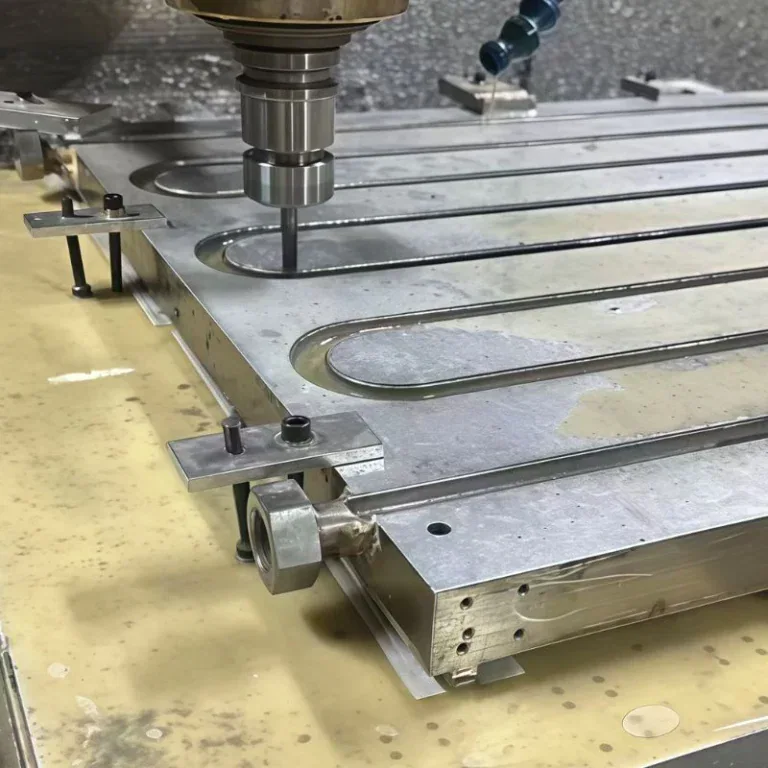
CNC milling is suitable for equipment bases, brackets, positioning blocks, and feeding tracks with complex slots. Drilling and tapping can be completed within the same setup on a machining center when the machining plan allows. CNC turning is mainly used for cylindrical components such as connecting shafts and sleeves, including their outer diameters, end faces, and mating features. For narrow slots, irregular contours, and other features that are difficult to machine through conventional milling, wire EDM or sinker EDM can be considered according to actual requirements. Proper planning of machining datums and operation sequences helps reduce dimensional errors caused by repeated setups.
Бүрэлдэхүүн хэсгийн хэрэглээний дагуу материалыг сонгоно уу
Materials should be selected based on component loads, contact frequency, and friction conditions.
| Бүрэлдэхүүн хэсгийн төрөл | Боломжит материалууд | Гол анхаарлууд |
| Equipment bases and brackets | Хөнгөн цагаан хайлш, нүүрстөрөгчийн ган | Хатуулаг, жин |
| Блок болон бэхэлгээг байрлуулах | Хөнгөн цагаан хайлш, хайлшин ган | Байршлын нарийвчлал, элэгдэлд тэсвэртэй байдал |
| Connecting shafts and sleeves | Хайлш ган, зэвэрдэггүй ган | Strength, dimensional fit |
| Feeding tracks and screw-separating structures | Aluminum alloys, brass, stainless steel, tool steel | Wear resistance, surface condition |
| Local guide components | Engineering plastics such as POM | Friction characteristics, dimensional stability |
Feeding tracks require particular attention to friction between the screws and contact surfaces. Aluminum alloy components can undergo hard anodizing when greater wear resistance is required. Brass, stainless steel, and appropriately treated steel can also be used for specific feeding structures. Engineering plastics are more suitable for certain local guide components or replaceable parts.
How to Ensure the Machining Quality of Automatic Screw Locking Machine Parts?
Quality inspections should focus on component functions and assembly requirements rather than checking external dimensions alone.
Inspect Critical Dimensions and Mating Relationships
After machining, the following features should be inspected:
- Hole positions and diameters: Check the dimensions and positions of mounting holes, locating holes, and clamping holes.
- Mating dimensions: Check shaft diameters, sleeve inner diameters, and the fit between connecting components.
- Geometric accuracy: Inspect parallelism, perpendicularity, and concentricity according to drawing requirements.
- Surface quality: Check for burrs, scratches, and surface roughness issues.
Feeding guide slots, bit mounting positions, and fixture locating surfaces should receive particular attention during inspection.
Arrange Surface Treatments According to Material
Different materials require suitable treatments to meet wear resistance, protection, and dimensional requirements.
- Aluminum alloy components: Standard anodizing or hard anodizing can be selected according to operating requirements.
- Steel components: Heat treatment or appropriate surface treatments can be arranged according to strength and wear resistance requirements.
- Screw-contact areas: Precision finishing, polishing, or wear-resistant treatments can improve surface conditions.
Surface treatments may affect component dimensions, so machining allowances for precision mating areas should be considered in advance.
What Should Buyers Prepare When Purchasing Automatic Screw Locking Machine Parts?
Complete technical documentation helps suppliers evaluate machining difficulty, production costs, and delivery arrangements.
Prepare Engineering Drawings and Technical Requirements
The following information should be provided before requesting a quotation:
- 2D engineering drawings: Specify dimensions, tolerances, hole positions, and surface roughness.
- 3D models: Clarify complex slots and component assembly relationships.
- Material requirements: Specify material grades and heat treatment or surface treatment requirements.
- Order information: Provide prototype quantities, batch requirements, and expected delivery schedules.
For feeding tracks and positioning fixtures, guide slot dimensions and critical mating requirements should be clearly specified.
Нийлүүлэгчийн машин механизмын чадварыг үнэлэх
When selecting a supplier, buyers should evaluate CNC milling, turning, precision inspection, and specialized structural machining capabilities. They should also confirm whether the supplier can coordinate heat treatment and surface treatment processes. For newly developed equipment, prototype machining can be arranged first to verify screw feeding, positioning, and fastening performance through actual assembly before establishing the batch production plan.
Automatic screw locking machine parts must meet requirements for smooth feeding, stable clamping, and accurate positioning. Selecting suitable materials and machining processes according to component applications, while controlling critical dimensions and surface quality, helps reduce problems during equipment assembly and operation. TiRapid provides customized CNC machining services based on customer drawings and project requirements, supporting prototype development and batch manufacturing of precision components for automatic screw locking machines.