Wafer handle systems move semiconductor wafers between carriers, aligners, process tools, inspection stations, and vacuum modules while maintaining accurate positioning and minimizing contamination or physical damage. Because wafers are thin, fragile, and increasingly valuable as they move through fabrication, even a small handling error can cause edge damage, particles, misalignment, or lost production time.
This guide explains how wafer handle systems work, how wafer handler robots and end effectors support automated transfer, and how vacuum contact and edge grip methods differ. It also covers alignment, vibration, cleanliness, precision component manufacturing, inspection, and the engineering factors that determine reliable wafer handling performance.
What Is A Wafer Handle System?
A wafer handle system is an automated mechanism that picks, supports, positions, transfers, and returns semiconductor wafers between carriers and process equipment. A complete system may include load ports, wafer handler robots, aligners, end effectors, sensors, load locks, and control software working together to move wafers accurately while limiting particles, vibration, and unnecessary contact.
What Does A Wafer Handler Do?
A wafer handler performs controlled wafer movement between different stations in semiconductor equipment.
Depending on the system, it may retrieve a wafer from a FOUP or cassette, move it to an aligner, transfer it into a process tool, and later return it to the assigned carrier slot.
The robot itself does not work alone. Its motion must be coordinated with wafer presence sensors, mapping data, alignment information, load-port status, and the end effector that physically supports the wafer.
Why Does Wafer Handling Require High Precision?
Wafers must arrive at each station in the correct position, height, and orientation.
Small positioning errors can interfere with process chucks, aligners, carriers, or transfer interfaces. Excess vibration can also cause the wafer to shift or increase settling time before the next process step begins.
Manufacturing Compass describes wafer transfer as a sequence in which the robot must limit contact, vibration, and particles while moving the wafer from the carrier toward downstream processing.
Where Is Wafer Handling Used In Semiconductor Manufacturing?
Wafer handling is used throughout front-end, inspection, sorting, transfer, coating, cleaning, and other automated semiconductor processes.
Atmospheric wafer handlers commonly operate between FOUPs, aligners, and process-tool entrances. Vacuum robots operate downstream of load locks, moving wafers between vacuum chambers without returning them to atmospheric pressure.
Wafer sorters are also used before inspection, after process steps, at quality-control stations, and between equipment with different carrier standards.
How Does A Wafer Handling System Work?
A typical wafer handling sequence follows a controlled path from carrier loading to mapping, picking, alignment, process-tool handoff, and return. Each stage must confirm wafer position and system status before the next movement begins, because a transfer fault can affect both the wafer and downstream equipment.
FOUP And Carrier Loading
The process usually begins when a FOUP or wafer carrier reaches a load port.
The load port secures the carrier and verifies that it is correctly seated before opening the controlled interface.
For 300 mm wafer systems, the FOUP provides a closed transport environment that helps protect wafers while they move between equipment.
Wafer Mapping And Identification
Before wafers are transferred, the system determines which carrier slots are occupied.
Wafer mapping helps identify missing wafers, double-loaded positions, and slot information before robot motion begins. Some systems also use OCR or laser-based identification to track individual wafers. Fortrend identifies wafer mapping and ID reading as core functions of automated wafer sorting systems.
Reliable mapping prevents the robot from entering an empty slot or attempting to pick wafers incorrectly.
Wafer Picking And Transfer
After the target wafer is identified, the wafer handler robot moves its end effector into the carrier.
The end effector supports or grips the wafer before it is withdrawn. The robot then follows a programmed motion path toward the next station.
During this stage, acceleration and deceleration must be controlled so the wafer remains stable while maintaining the required throughput.
Wafer Alignment And Orientation
Before entering many process tools, the wafer must be centered and rotationally oriented.
The aligner identifies the wafer center and the notch or flat orientation so that the next station receives it in the correct position. Manufacturing Compass places alignment immediately before the handoff stage in a typical FOUP-to-tool sequence.
Correct alignment improves repeatability for later processing and reduces the amount of correction required by downstream equipment.
Handoff To The Process Tool Or Load Lock
After alignment, the wafer is delivered either to an atmospheric process station or to a load lock.
A load lock separates the atmospheric transfer environment from the vacuum side of the equipment. Once pressure conditions are established, a vacuum robot can move the wafer between process chambers.
Festo demonstrates this transition using a transfer valve and vacuum chamber, with controlled wafer movement designed to minimize vibration and particle generation.
Wafer Return And Tracking
After processing, the wafer is returned to the correct carrier or assigned destination.
Control software tracks slot information, wafer history, process status, and transfer exceptions. This traceability becomes particularly important when wafers are sorted, rerouted, or moved between multiple stations.
Automated wafer sorters may also use mapping and ID data to maintain processing history and lot traceability.
What Components Make Up A Wafer Handling System?
A complete wafer handling system combines mechanical transfer hardware, sensing, alignment, environmental control, and software. The most important components include load ports, carriers, wafer handler robots, aligners, end effectors, load locks, vacuum transfer modules, and sensors that verify wafer position and equipment status.
Load Ports And Wafer Carriers
Load ports create the controlled interface between the wafer carrier and semiconductor equipment.
They position the carrier, operate the door, support mapping, and coordinate access with the robot.
The carrier protects wafers outside the tool and maintains an organized slot structure for automated transfer.
Wafer Handler Robots
A wafer handler robot provides the programmed motion required to move wafers between stations.
Robot configurations vary depending on equipment architecture, travel distance, available space, atmospheric or vacuum operation, and required throughput.
The mechanical arm, servo system, end effector, and sensors must operate as one coordinated assembly.
Wafer Aligners And Sorters
Aligners establish wafer center and rotational orientation.
Sorters perform broader functions such as cassette-to-cassette transfer, ID reading, mapping, alignment, flipping, or recipe-based wafer rearrangement.
These systems are important when wafers need to be organized, tracked, or prepared before inspection and processing.
Wafer Handling End Effectors
The wafer handling end effector is the robot component that directly supports or holds the wafer.
Its design determines where the wafer is contacted, how holding force is generated, and how efficiently the robot can move through restricted equipment spaces.
Fortrend identifies vacuum contact and edge grip as two widely used end-effector approaches.
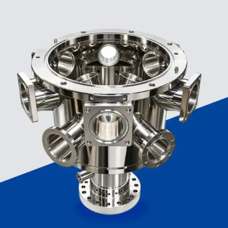
Load Locks And Vacuum Transfer Modules
Load locks allow wafers to move between atmospheric pressure and vacuum without venting the complete process system.
A vacuum transfer module then uses a vacuum-compatible robot to move wafers among process chambers.
This separation is important because atmospheric EFEM handling and vacuum transfer operate under different environmental and material requirements.
Sensors, Mapping, And Control Systems
Sensors verify wafer presence, carrier position, robot position, pressure condition, and transfer status.
Mapping systems identify wafer slot conditions, while aligners and ID readers supply position and tracking data.
Software coordinates these signals so mechanical motion only occurs when the next transfer step is safe.
What Wafer Handling Methods Are Commonly Used?
The two most common wafer holding approaches are vacuum contact and edge grip. Vacuum contact uses pressure differential to hold the wafer against defined contact areas, while edge grip mechanically supports the wafer around its perimeter. The correct method depends on wafer geometry, cleanliness requirements, robot dynamics, and equipment architecture.
Vacuum Contact Handling
Vacuum contact handling uses lower pressure between the wafer and the end effector to create holding force.
Vacuum ports or channels can be distributed across the contact area to provide stable support. This approach can provide reliable retention during acceleration, deceleration, and robot rotation.
Its main limitation is backside contact. If the process places strict restrictions on wafer backside cleanliness, contact location and surface quality must be carefully controlled.
Edge Grip Handling
Edge grip handling supports the wafer at its outer perimeter instead of using suction across the wafer surface.
This reduces broad backside contact and can be useful when surface cleanliness is especially important.
However, gripping force must be carefully controlled. Excessive or uneven load can create localized stress, particularly on thin, fragile, warped, or edge-sensitive wafers.
Vacuum Contact Vs Edge Grip
Vacuum contact offers stable active retention and is well suited to dynamic transfer when the vacuum interface is designed correctly.
Edge grip reduces backside contact and does not require a vacuum source, but it introduces mechanical contact at the wafer edge.
Neither method is universally better. Selection depends on process requirements rather than a general preference.
How Wafer Size And Thickness Affect Method Selection
Larger wafers require careful support distribution because bending behavior changes as diameter increases.
Thin wafers have lower rigidity and may require more distributed support or lower gripping force.
Fortrend notes that wafer size and thickness directly influence the end-effector design and the required handling force.
How Surface Condition And Cleanliness Affect Method Selection
The allowable contact area is often determined by the wafer surface condition.
If backside contact must be minimized, edge grip may be preferable. If strong retention during high-speed motion is more important, vacuum handling may provide advantages.
Both methods still need to be evaluated for particle generation and contact-related contamination.
How Is A Wafer Handling End Effector Designed?
A wafer handling end effector must support the wafer securely while remaining lightweight, stiff, clean, and compatible with the robot’s motion envelope. Contact geometry, vacuum passages, gripping force, material selection, and feature accuracy all influence transfer stability.
Wafer Contact And Support Geometry
The support geometry determines how forces are distributed across the wafer.
Vacuum designs use defined contact areas, while edge-grip systems concentrate support around the perimeter.
The geometry should avoid unnecessary contact while maintaining enough support to prevent wafer motion during transfer.
Vacuum Ports And Internal Channels
Vacuum end effectors require ports or internal channels that distribute suction to the intended contact locations.
These channels must be open, clean, and free from burrs or machining residue.
Poorly controlled internal geometry can create uneven holding force or reduce vacuum response.
Edge Grip Contact And Force Control
Edge-grip end effectors require accurate contact locations and controlled motion.
Grip force should be strong enough to secure the wafer but not so high that it creates edge stress.
The mechanism must also accommodate manufacturing variation in wafer thickness and any expected warpage.
Weight, Stiffness, And Low-Inertia Design
The end effector moves repeatedly at the end of the robot arm, so unnecessary mass increases inertia.
Lower mass can improve acceleration and settling behavior, but excessive weight reduction may reduce stiffness.
This creates a design tradeoff between lightweight structure, vibration resistance, and mechanical stability.
Clearance, Alignment, And Robot Integration
The end effector must fit into wafer carriers, aligners, load locks, and process stations without collision.
Edge-grip mechanisms require enough perimeter clearance to reach the wafer edge, while vacuum designs must maintain the correct support height.
Fortrend emphasizes that end effectors cannot be evaluated separately from robot kinematics, motion control, detection, mapping, alignment, and load ports.
What Determines Wafer Handling Accuracy And Stability?
Wafer handling accuracy depends on robot positioning, end-effector geometry, wafer centering, handoff height, vibration, acceleration, and wafer condition. Reliable transfer requires repeatable mechanical relationships between the carrier, robot, aligner, and destination station.
Positioning Accuracy And Repeatability
Positioning accuracy determines how closely the robot reaches the commanded location.
Repeatability describes how consistently it returns to the same position over repeated cycles.
For wafer transfer, repeatability is especially important because even a small recurring offset can affect slot entry, alignment, or process-tool handoff.
Wafer Centering And Orientation
The wafer should be centered before reaching process equipment.
Aligners detect center position and notch or flat orientation so the robot can compensate for carrier loading variation.
This reduces dependence on the original wafer position inside the FOUP or cassette.
Handoff Height And Motion Accuracy
The Z-height of the wafer must match the receiving station.
If the handoff is too high or too low, the wafer may contact guides, pins, chuck surfaces, or other hardware.
Mechanical tolerances in robot arms, end effectors, mounts, and receiving fixtures therefore contribute to the total handoff accuracy.
Vibration, Acceleration, And Settling Time
High acceleration improves throughput but increases dynamic load.
A flexible end effector can vibrate after the robot stops, forcing the system to wait before the next operation begins.
Festo specifically emphasizes low-vibration transfer and controlled wafer placement in vacuum process applications.
Thin, Fragile, And Warped Wafer Handling
Thin and warped wafers require additional support because they are less rigid than standard wafers.
Vacuum force must not create unwanted deformation, while edge-grip force must not overstress the perimeter.
The support geometry should therefore match the wafer condition instead of assuming all wafers behave the same way.
How Are Cleanliness And Particle Control Maintained?
Clean wafer handling requires minimizing unnecessary contact, controlling the surface condition of end effectors, selecting cleanroom-compatible materials, and preventing particles or residues from entering the transfer environment. Cleanliness must be maintained through both component design and routine maintenance.
Minimizing Wafer Contact
Every contact point creates a potential contamination or marking risk.
Handling systems therefore use defined support regions rather than allowing uncontrolled surface contact.
Edge gripping can reduce backside contact, while vacuum handling limits contact to specified vacuum support areas.
End Effector Surface Quality
End-effector surfaces should be free from burrs, sharp edges, loose particles, and heavy machining marks.
Contact features need consistent geometry so the wafer does not rest on isolated high points.
Surface finishing should improve cleanliness without changing critical contact dimensions.
Cleanroom-Compatible Materials
Materials should be selected for mechanical stability, low particle generation, chemical compatibility, and the operating environment.
Aluminum, stainless steel, engineering plastics, and other materials may be used depending on the design.
Vacuum-side components also need materials, seals, and lubricants compatible with the required vacuum and contamination limits.
Vacuum Lines And Contact Surface Cleanliness
Vacuum passages should remain free from chips, oils, and debris.
Contamination inside a small vacuum channel can reduce suction or migrate toward the wafer contact area.
Internal deburring and controlled cleaning are therefore important after machining.
Cleaning And Maintenance Of Handling Components
End effectors and contact surfaces require periodic inspection and cleaning.
Particles can accumulate during normal equipment operation, especially at repeated contact points.
Maintenance procedures should protect alignment and contact geometry rather than treating the end effector as a simple replaceable plate.
How Are Wafer Handling Components Manufactured?
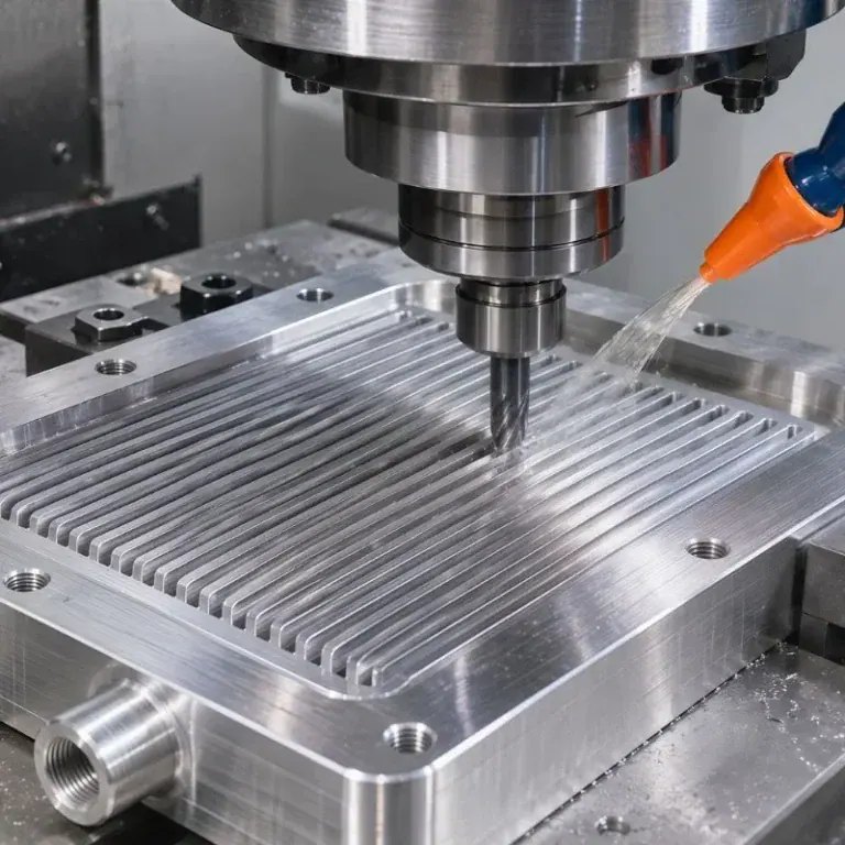
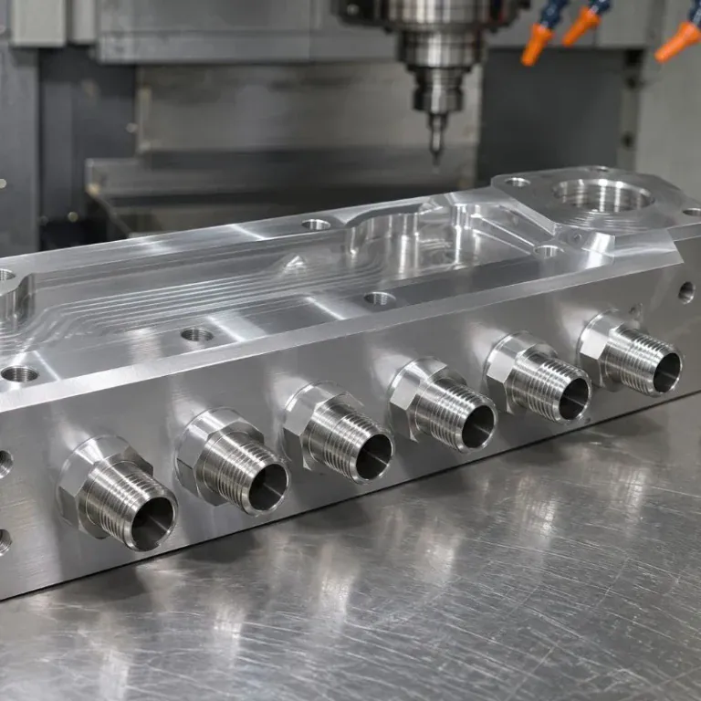
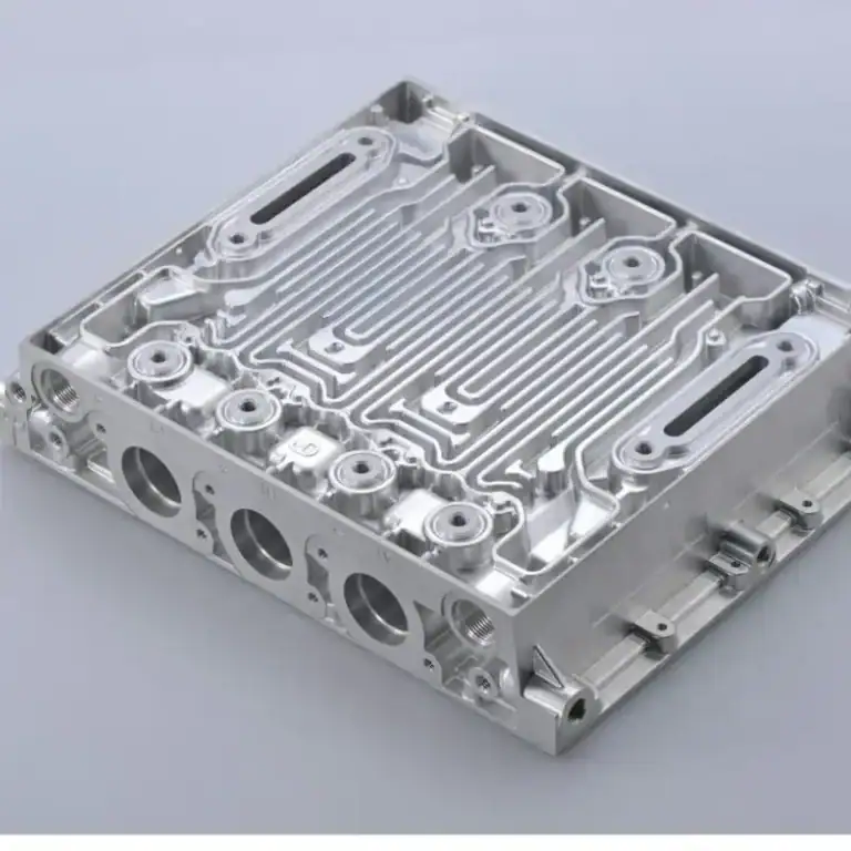
Wafer handling components are commonly produced through precision CNC milling, turning, and multi-axis machining. End effectors and robot components often combine thin walls, low mass, small vacuum channels, precision mounting features, and clean surfaces, so machining strategy must control both geometry and contamination risks.
CNC Machining Of Wafer Handling End Effectors
End effectors may be machined from aluminum, stainless steel, PEEK, or other engineering materials depending on the application.
Critical features can include vacuum ports, channels, contact pads, mounting holes, locating interfaces, and lightweight pockets.
Machining should maintain the relationship between the wafer-support surface and the robot mounting datum.
Precision Machining Of Robot Arms And Mounting Parts
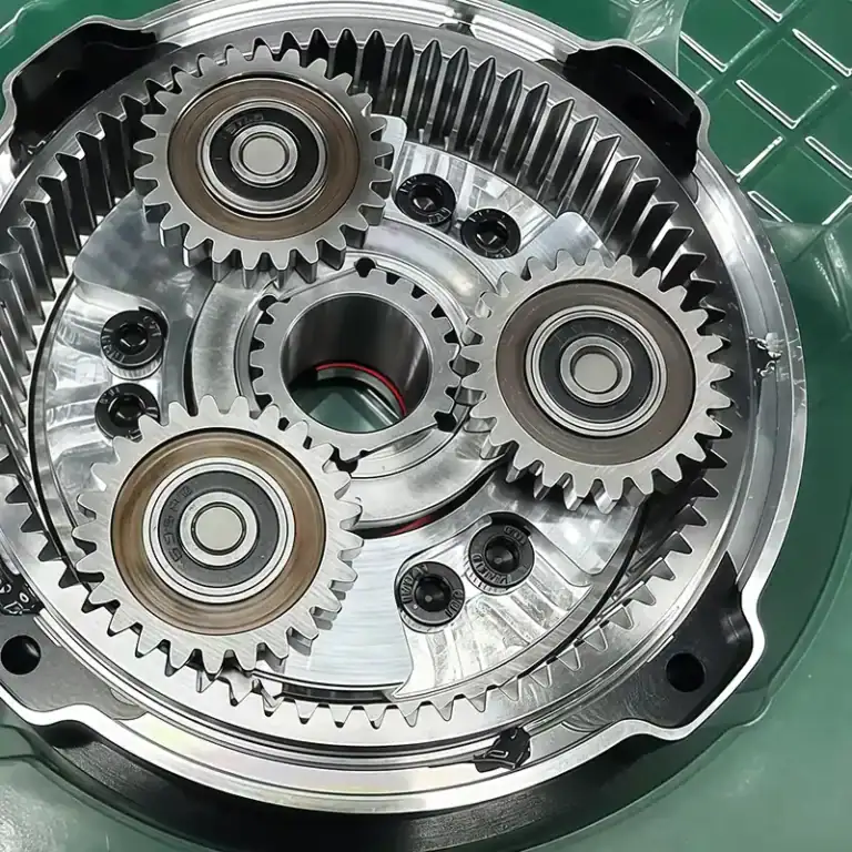
Robot arms and mounting components require accurate interfaces so the complete mechanism maintains alignment.
Hole positions, bearing interfaces, mounting faces, and datum surfaces influence the final motion system.
Where multiple surfaces are functionally related, reducing setup changes can improve positional consistency.
Thin-Wall And Lightweight Aluminum Machining
Lightweight robot components often use thin walls and pocketed aluminum structures.
These parts are efficient in motion systems but can distort during machining.
Balanced stock removal, low cutting forces, stable workholding, and final inspection after unclamping help reduce geometric variation.
PEEK And Engineering Plastic Components
PEEK and similar engineering plastics may be used for insulating, supporting, or contact-related parts.
These materials have different thermal expansion and stiffness behavior from aluminum.
Cutting parameters and clamping force should therefore be controlled to prevent heat or fixture pressure from changing the finished dimensions.
Surface Finish, Edge Control, And Burr Removal
Burrs are especially undesirable near wafer contact areas or internal vacuum channels.
Edges should be controlled according to the drawing rather than aggressively rounded during manual finishing.
Internal channels should also be inspected after deburring to confirm that the vacuum path remains clear.
How Are Wafer Handling Components Inspected And Verified?
Inspection should verify dimensional accuracy, flatness, vacuum-channel condition, surface quality, and assembly alignment. Because wafer handling depends on the relationship between multiple components, inspection should focus on functional datums rather than checking individual dimensions in isolation.
Dimensional And CMM Inspection
CMM inspection can verify mounting holes, profiles, locating features, and relationships between the wafer-support area and robot interface.
Critical dimensions should reference the same datum system used by the engineering drawing.
This improves the connection between measurement results and actual assembly function.
Flatness And Profile Inspection
Flatness matters where the end effector provides distributed support beneath the wafer.
Profile inspection is useful for lightweight arms or complex contact surfaces.
Measurement should confirm that machining and unclamping have not introduced distortion into thin sections.
Vacuum Port And Internal Channel Inspection
Small vacuum holes should be checked for diameter, position, blockage, and burrs.
Internal channels should remain fully connected to the intended vacuum ports.
Airflow checks or other functional verification may be used when dimensional inspection alone cannot confirm the complete internal path.
Surface And Cleanliness Inspection
Visual inspection can identify scratches, dents, burrs, residue, or foreign particles.
Where the drawing specifies roughness or cleanliness requirements, appropriate measurement or verification methods should be used.
The final condition should be maintained during packaging and assembly.
Assembly, Alignment, And Motion Verification
Individual component inspection does not guarantee correct robot motion.
The assembled wafer handler may require alignment checks, end-effector height verification, motion testing, and transfer simulation.
Festo’s integrated example illustrates how end-effector positioning, wafer alignment, transfer valves, and wafer chucks must operate as one coordinated system.
What Common Problems Occur In Wafer Handling?
Common wafer handling problems include wafer slipping, contamination, alignment errors, excessive vibration, edge damage, mapping faults, and incorrect picks. These problems often result from several interacting causes rather than one isolated robot error.
Wafer Slipping Or Dropping
Vacuum loss, insufficient gripping force, contaminated contact areas, or aggressive robot motion can reduce wafer stability.
The system should verify that the wafer is securely held before high-speed transfer begins.
Holding force should also match the wafer type and motion profile.
কণা দূষণ
Particles can come from contact surfaces, worn mechanisms, loose burrs, seals, or the surrounding environment.
Repeated contact can make even a small surface defect a continuing contamination source.
Clean design and regular maintenance are therefore equally important.
Alignment And Positioning Errors
Incorrect wafer center, notch orientation, robot calibration, or fixture location can cause transfer errors.
Alignment systems reduce this risk by establishing the wafer’s actual position before handoff.
Mapping and sensor data must also remain synchronized with robot motion.
Excessive Vibration Or Long Settling Time
Flexible arms, heavy end effectors, aggressive acceleration, or loose mechanical interfaces can increase vibration.
The wafer may remain secure but still require extra time before the next process step.
Improving stiffness and reducing unnecessary moving mass can support both precision and throughput.
Wafer Edge Damage And Contact Marks
Edge-grip systems can damage the wafer if gripping force is excessive or the contact geometry is incorrect.
Vacuum systems can leave unwanted backside contact marks when the interface is unsuitable for the process.
Handling method and contact design should therefore follow the wafer’s actual surface and edge requirements.
Double Picks, Mapping Errors, And Transfer Faults
Incorrect slot mapping can cause the robot to approach the wrong wafer position.
Wafer sorters and load ports use mapping and identification systems to detect wafer presence and support traceability.
Sensors and software interlocks help prevent the robot from continuing when the transfer condition is uncertain.
How Should A Wafer Handling System Be Selected?
A wafer handling system should be selected according to wafer size, thickness, material, contact restrictions, transfer environment, robot speed, cleanliness requirements, and equipment integration. The best system is the one that protects the wafer while meeting the required throughput and process conditions.
Wafer Size, Thickness, And Material
Wafer dimensions influence support geometry, robot payload, and gripping method.
Larger wafers need appropriate support distribution, while thin or fragile substrates may require lower contact forces.
The system should also consider whether future wafer formats need to be supported.
Vacuum Contact Or Edge Grip Requirements
Vacuum contact is suitable when stable retention and dynamic motion are priorities and backside contact is acceptable.
Edge grip is attractive where backside contact should be minimized or no vacuum source is available.
Fortrend recommends evaluating the complete application rather than choosing one method universally.
Atmospheric Or Vacuum Transfer Environment
Atmospheric handling systems can use a broader range of materials and actuation methods.
Vacuum transfer requires compatible materials, lubricants, seals, sensors, and mechanical structures.
The system boundary between EFEM handling, load lock, and vacuum transfer should therefore be clearly defined.
Robot Speed And Throughput Requirements
Higher robot speed can improve tool throughput, but only if the wafer remains stable and settling time does not increase excessively.
The complete transfer sequence should be evaluated rather than focusing on maximum robot speed alone.
Carrier opening, mapping, alignment, handoff, and return all contribute to total cycle time.
Cleanliness And Particle Requirements
Contact surfaces, moving mechanisms, airflow, materials, and maintenance practices all influence particle performance.
Applications with stricter cleanliness requirements may favor handling methods that reduce contact or simplify contamination control.
The actual process specification should determine the acceptable solution.
Equipment Integration And Maintenance
The wafer handler must integrate with load ports, aligners, process tools, sensors, control software, and safety systems.
Mechanical access for adjustment and maintenance is also important.
A design that performs well in isolation may create long-term problems if calibration, cleaning, or end-effector replacement is difficult.
বিবরণ
What Is The Difference Between A Wafer Handler And A Wafer Handling System?
A wafer handler usually refers to the robot or mechanism that physically transfers the wafer. A wafer handling system is broader and may include the robot, load ports, carriers, aligners, end effectors, sensors, load locks, mapping systems, and control software required to complete the transfer sequence.
Is Vacuum Contact Or Edge Grip Better For Wafer Handling?
Neither method is universally better. Vacuum contact provides stable retention and is useful for dynamic transfer when backside contact is acceptable. Edge grip minimizes broad surface contact but requires careful control of edge force and clearance. Wafer thickness, surface condition, cleanliness, robot speed, and equipment architecture should determine the final choice.
What Makes A Wafer Handling End Effector Difficult To Machine?
End effectors often combine thin walls, low mass, tight mounting relationships, small vacuum passages, and precision wafer-contact features. Removing too much material can cause distortion, while burrs inside vacuum holes can affect holding performance. Machining should therefore control rigidity, datum relationships, internal cleanliness, and final surface condition together.
How Can Wafer Handling Accuracy Be Verified?
Verification can include dimensional and CMM inspection of components, end-effector flatness or profile checks, vacuum-path inspection, assembly alignment, robot calibration, handoff-height checks, and transfer testing. The inspection plan should focus on the complete functional relationship between the robot, end effector, wafer, and receiving station.
উপসংহার
Reliable wafer handling depends on more than robot motion alone. The carrier interface, mapping system, aligner, wafer handler robot, end effector, gripping method, mechanical accuracy, cleanliness, and inspection process must work together as one controlled transfer system. Selecting the correct handling method and maintaining precise, clean mechanical components helps reduce wafer damage, contamination, alignment errors, and unnecessary transfer delays.
At টিআরপিড, we provide precision CNC machining and manufacturing services for semiconductor automation components, including wafer handling end effectors, lightweight robot parts, mounting components, vacuum-channel parts, and other complex aluminum and engineering plastic components. Our 3-axis, 4-axis, and 5-axis machining capabilities support DFM, thin-wall machining, precision features, dimensional inspection, and repeat production for semiconductor equipment projects.